
User Manual

MPU-9250 Register Map and Descriptions
Document Number: RM-MPU-9250A-00
Revision: 1.4
Release Date: 9/9/2013
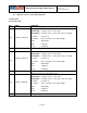
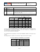
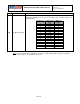
BIT
NAME
FUNCTION
[2]
SLV_2
1 – write EXT_SENS_DATA registers associated to SLV_2 (as determined by
I2C_SLV0_CTRL, I2C_SLV1_CTRL, and I2C_SL20_CTRL) to the FIFO at
the sample rate;
0 – function is disabled
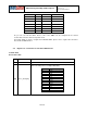
[1]
SLV_1
1 – write EXT_SENS_DATA registers associated to SLV_1 (as determined by
I2C_SLV0_CTRL and I2C_SLV1_CTRL) to the FIFO at the sample rate;
0 – function is disabled
[0]
SLV_0
1 – write EXT_SENS_DATA registers associated to SLV_0 (as determined by
I2C_SLV0_CTRL) to the FIFO at the sample rate;
0 – function is disabled
NOTE: See I2C_SLV3_CTRL register to enable this feature for SLV_3
Note: For further information regarding the association of EXT_SENS_DATA registers to particular
slave devices, please refer to Registers 73 to 96.
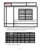
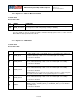
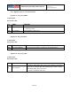
4.12 Register 36 – I2C Master Control
Serial IF: R/W
Reset value: 0x00
BIT
NAME
FUNCTION
[7]
MULT_MST_EN
Enables multi-master capability. When disabled, clocking to the I2C_MST_IF
can be disabled when not in use and the logic to detect lost arbitration is
disabled.
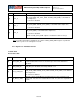
[6]
WAIT_FOR_ES
Delays the data ready interrupt until external sensor data is loaded. If
I2C_MST_IF is disabled, the interrupt will still occur.
[5]
SLV_3_FIFO_EN
1 – write EXT_SENS_DATA registers associated to SLV_3 (as determined by
I2C_SLV0_CTRL and I2C_SLV1_CTRL and I2C_SLV2_CTRL) to the FIFO at
the sample rate;
0 – function is disabled
[4]
I2C_MST_P_NSR
This bit controls the I2C Master’s transition from one slave read to the next
slave read. If 0, there is a restart between reads. If 1, there is a stop between
reads.
18 of 55