
User Manual

MPU-9250 Register Map and Descriptions
Document Number: RM-MPU-9250A-00
Revision: 1.4
Release Date: 9/9/2013
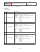
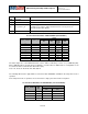
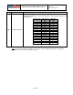
[5:3]
EXT_SYNC_SET[2:0]
Enables the FSYNC pin data to be sampled.
EXT_SYNC_SET
FSYNC bit location
0
function disabled
1
TEMP_OUT_L[0]
2
GYRO_XOUT_L[0]
3
GYRO_YOUT_L[0]
4
GYRO_ZOUT_L[0]
5
ACCEL_XOUT_L[0]
6
ACCEL_YOUT_L[0]
7
ACCEL_ZOUT_L[0]
Fsync will be latched to capture short strobes. This will be done such that if
Fsync toggles, the latched value toggles, but won’t toggle again until the new
latched value is captured by the sample rate strobe. This is a requirement for
working with some 3
rd
party devices that have fsync strobes shorter than our
sample rate.
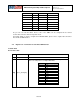
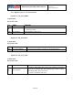
[2:0]
DLPF_CFG[2:0]
For the DLPF to be used, fchoice[1:0] must be set to 2’b11, fchoice_b[1:0] is
2’b00.
See table 3 below.
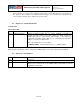
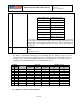
The DLPF is configured by DLPF_CFG, when FCHOICE_B [1:0] = 2b’00. The gyroscope and
temperature sensor are filtered according to the value of DLPF_CFG and FCHOICE_B as shown in
the table below. Note that FCHOICE mentioned in the table below is the inverted value of
FCHOICE_B (e.g. FCHOICE=2b’00 is same as FCHOICE_B=2b’11).
FCHOICE
DLPF_CFG
Gyroscope
Temperature Sensor
<1> <0>
Bandwidth
(Hz)
Delay
(ms)
Fs (kHz)
Bandwidth
(Hz)
Delay
(ms)
x
0
x
8800
0.064
32
4000
0.04
0
1
x
3600
0.11
32
4000
0.04
1
1
0
250
0.97
8
4000
0.04
1
1
1
184
2.9
1
188
1.9
1 1 2 92 3.9 1 98 2.8
1
1
3
41
5.9
1
42
4.8
1
1
4
20
9.9
1
20
8.3
1
1
5
10
17.85
1
10
13.4
1
1
6
5
33.48
1
5
18.6
1
1
7
3600
0.17
8
4000
0.04
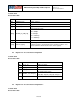
4.6 Register 27 – Gyroscope Configuration
13 of 55