
Data Sheet

MPU-9250 Product Specification
Document Number: PS-MPU-9250A-01
Revision: 1.0
Release Date: 01/17/2014
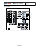
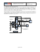
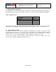
4.13 MPU-9250 Solution Using I2C Interface
In the figure below, the system processor is an I
2
C master to the MPU-9250. In addition, the MPU-9250 is an
I
2
C master to the optional external 3
rd
party sensor. The MPU-9250 has limited capabilities as an I
2
C Master,
and depends on the system processor to manage the initial configuration of any auxiliary sensors. The MPU-
9250 has an interface bypass multiplexer, which connects the system processor I
2
C bus (SDA and SCL)
directly to the auxiliary sensor I
2
C bus (AUX_DA and AUX_CL).
Once the auxiliary sensors have been configured by the system processor, the interface bypass multiplexer
should be disabled so that the MPU-9250 auxiliary I
2
C master can take control of the sensor I
2
C bus and
gather data from the auxiliary sensors. The INT pin should be connected to a GPIO on the system processor
that can wake the system from suspend mode.
MPU-9250
AD0
SCL
SDA/SDI
Digital
Motion
Processor
(DMP)
Sensor
Master I
2
C
Serial
Interface
AUX_CL
AUX_DA
Interrupt
Status
Register
INT
VDD
Bias & LDOs
GND REGOUT
FIFO
User & Config
Registers
Sensor
Register
Factory
Calibration
Slave I
2
C
or SPI
Serial
Interface
3
rd
party
sensor
SCL
SDA
System
Processor
Interface
Bypass
Mux
SCL
SDA
VDD or GND
I
2
C Processor Bus: for reading all
sensor data from MPU and for
configuring external sensors (i.e.
compass in this example)
Interface bypass mux allows
direct configuration of
compass by system processor
Optional
Sensor I
2
C Bus: for
configuring and reading
from external sensors
VDDIO
Page 25 of 42