
Data Sheet

MPU-9250 Product Specification
Document Number: PS-MPU-9250A-01
Revision: 1.0
Release Date: 01/17/2014
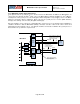
Pass-Through mode is useful for configuring the external sensors, or for keeping the MPU-9250 in a
low-power mode when only the external sensors are used. In this mode, the system processor can
still access MPU-9250 data through the I
2
C interface.
Pass-Through mode is also used to access the AK8963 magnetometer directly from the host. In this
configuration the slave address for the AK8963 is 0X0C or 12 decimal.
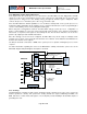
Auxiliary I
2
C Bus IO Logic Levels
For MPU-9250, the logic level of the auxiliary I
2
C bus is VDDIO. For further information regarding the MPU-
9250 logic levels, please refer to Section 10.2.
4.12 Self-Test
Please refer to the register map document for more details on self-test.
Self-test allows for the testing of the mechanical and electrical portions of the sensors. The self-test for eac h
measurement axis can be activated by means of the gyroscope and accelerometer self-test registers
(registers 13 to 16).
When the self-test is activated, the electronics cause the sensors to be actuated and produce an output
signal. The output signal is used to observe the self-test response.
The self-test response is defined as follows:
Self-test response = Sensor output with self-test enabled – Sensor output without self-test enabled
When the value of the self-test response is within the appropriate limits, the part has passed self-test. When
the self-test response exceeds the appropriate values, the part is deemed to have failed self-test. It is
recommended to use InvenSense MotionApps software for executing self-test. Further details, including the
self-test limits are included in the MPU-9250 Self-Test applications note available from InvenSense.
Page 24 of 42