
Data Sheet

MPU-9250 Product Specification
Document Number: PS-MPU-9250A-01
Revision: 1.0
Release Date: 01/17/2014
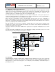
gyroscopes, magnetometers and additional 3
rd
party sensors, and processes the data. The resulting data can
be read from the DMP’s registers, or can be buffered in a FIFO. The DMP has access to one of the MPU’s
external pins, which can be used for generating interrupts. This pin (pin 12) should be connected to a pin on
the host processor that can wake the host from suspend mode.
The purpose of the DMP is to offload both timing requirements and processing power from the host
processor. Typically, motion processing algorithms should be run at a high rate, often around 200Hz, in order
to provide accurate results with low latency. This is required even if the application updates at a much lower
rate; for example, a low power user interface may update as slowly as 5Hz, but the motion processing should
still run at 200Hz. The DMP can be used as a tool in order to minimize power, simplify timing, simplify the
software architecture, and save valuable MIPS on the host processor for use in the application.
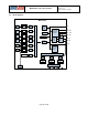
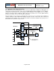
4.10 Primary I2C and SPI Serial Communications Interfaces
The MPU-9250 communicates to a system processor using either a SP I or an I
2
C serial interface. The MPU-
9250 always acts as a slave when communicating to the system processor. The LSB of the of the I
2
C slave
address is set by pin 9 (AD0).
4.11 Auxiliary I2C Serial Interface
The MPU-9250 has an auxiliary I
2
C bus for communicating to off-chip sensors. This bus has two operating
modes:
• I
2
C Master Mode: The MPU-9250 acts as a master to any external sensors connected to the
auxiliary I
2
C bus
• Pass-Through Mode: The MPU-9250 directly connects the primary and auxiliary I
2
C buses together,
allowing the system processor to directly communicate with any external sensors.
• Note: AUX_DA and AUX_CL should be left unconnected if the Auxiliary I
2
C mode is not used.
Auxiliary I
2
C Bus Modes of Operation:
• I
2
C Master Mode: Allows the MPU-9250 to directly access the data registers of external digital
sensors, such as a magnetometer. In this mode, the MPU-9250 directly obtains data from auxiliary
sensors without intervention from the system applications processor.
For example, In I
2
C Master mode, the MPU-9250 can be configured to perform burst reads, returning
the following data from a magnetometer:
X magnetometer data (2 bytes)
Y magnetometer data (2 bytes)
Z magnetometer data (2 bytes)
The I
2
C Master can be configured to read up to 24 bytes from up to 4 auxiliary sensors. A fifth sensor
can be configured to work single byte read/write mode.
• Pass-Through Mode: Allows an external system processor to act as master and directly
communicate to the external sensors connected to the auxiliary I
2
C bus pins (AUX_DA and
AUX_CL). In this mode, the auxiliary I
2
C bus control logic (3
rd
party sensor interface block) of the
MPU-9250 is disabled, and the auxiliary I
2
C pins AUX_DA and A UX_CL are connected to the main
I
2
C bus through analog switches internally.
Page 23 of 42