
Manual


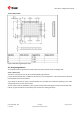


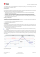
Table Of Contents
- Title
- Contents
- 1 Integration manual structure
- 2 System description
- 3 Receiver functionality
- 3.1 Receiver configuration
- 3.1.1 Changing the receiver configuration
- 3.1.2 Default GNSS configuration
- 3.1.3 Default interface settings
- 3.1.4 Basic receiver configuration
- 3.1.5 Differential timing mode configuration
- 3.1.6 Legacy configuration interface compatibility
- 3.1.7 Navigation configuration
- 3.2 Geofencing
- 3.3 Logging
- 3.4 Communication interfaces
- 3.5 Predefined PIOs
- 3.6 Antenna supervisor
- 3.7 Multiple GNSS assistance (MGA)
- 3.8 Clocks and time
- 3.9 Timing functionality
- 3.10 Security
- 3.11 u-blox protocol feature descriptions
- 3.12 Forcing a receiver reset
- 3.13 Firmware upload
- 3.1 Receiver configuration
- 4 Design
- 5 Product handling
- Appendix
- Related documents
- Revision history
- Contact

ZED-F9T-Integration manual
5 Product handling
5.1 ESD handling precautions
ZED-F9T contains highly sensitive electronic circuitry and is an Electrostatic Sensitive
Device (ESD). Observe precautions for handling! Failure to observe these precautions can
result in severe damage to the GNSS receiver!
•
Unless there is a galvanic coupling between the local
GND (i.e. the work table) and the PCB GND, then the first
point of contact when handling the PCB must always be
between the local GND and PCB GND.
•
Before mounting an antenna patch, connect ground of the
device.
•
When handling the RF pin, do not come into contact with
any charged capacitors and be careful when contacting
materials that can develop charges (e.g. patch antenna
~10 pF, coax cable ~50-80 pF/m or soldering iron).
•
To prevent electrostatic discharge through the RF input,
do not touch any exposed antenna area. If there is any risk
that such exposed antenna area is touched in non-ESD
protected work area, implement proper ESD protection
measures in the design.
•
When soldering RF connectors and patch antennas to the
receiver’s RF pin, make sure to use an ESD-safe soldering
iron (tip)
5.2 Soldering
Soldering paste
Use of “no clean” soldering paste is highly recommended, as it does not require cleaning after the
soldering process. The paste in the example below meets these criteria.
• Soldering paste: OM338 SAC405 / Nr.143714 (Cookson Electronics)
• Alloy specification: Sn 95.5/ Ag 4/ Cu 0.5 (95.5% tin/ 4% silver/ 0.5% copper)
• Melting temperature: 217 °C
• Stencil thickness: The exact geometry, distances, stencil thicknesses and solder paste
volumes must be adapted to the customer's specific production processes (e.g. soldering).
Reflow soldering
A convection-type soldering oven is highly recommended over the infrared-type radiation oven.
Convection-heated ovens allow precise control of the temperature, and all parts will heat up evenly,
regardless of material properties, thickness of components and surface color.
UBX-19005590 - R05
5 Product handling Page 79 of 87
C1-Public Early production information