
Manual


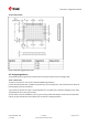


Table Of Contents
- Title
- Contents
- 1 Integration manual structure
- 2 System description
- 3 Receiver functionality
- 3.1 Receiver configuration
- 3.1.1 Changing the receiver configuration
- 3.1.2 Default GNSS configuration
- 3.1.3 Default interface settings
- 3.1.4 Basic receiver configuration
- 3.1.5 Differential timing mode configuration
- 3.1.6 Legacy configuration interface compatibility
- 3.1.7 Navigation configuration
- 3.2 Geofencing
- 3.3 Logging
- 3.4 Communication interfaces
- 3.5 Predefined PIOs
- 3.6 Antenna supervisor
- 3.7 Multiple GNSS assistance (MGA)
- 3.8 Clocks and time
- 3.9 Timing functionality
- 3.10 Security
- 3.11 u-blox protocol feature descriptions
- 3.12 Forcing a receiver reset
- 3.13 Firmware upload
- 3.1 Receiver configuration
- 4 Design
- 5 Product handling
- Appendix
- Related documents
- Revision history
- Contact

ZED-F9T-Integration manual
Figure 44: VCC pads
4.8 Design guidance
4.8.1 General considerations
Do not load Pin 4 (ANT_DETECT) with a capacitance more than 1 nF.
Check power supply requirements and schematic:
• Is the power supply voltage within the specified range and noise-free?
• If USB is not used, connect the V_USB pin to ground.
• It is recommended to have a separate LDO for V_USB that is enabled by the module VCC. This is
to comply with the USB self-powered specification.
• If USB is used, is there a 1 uF capacitor right near the V_USB pin? This is just for the V_USB pin.
• Is there a 1 uF cap right next to the module VCC pin?
• Compare the peak current consumption of the ZED-F9T GNSS module with the specification of
your power supply.
• GNSS receivers require a stable power supply. Avoid series resistance (less than 0.2 Ω) in
your power supply line (the line to VCC) to minimize the voltage ripple on VCC. See the ZED-
F9T Power supply section in the Design chapter for more information on the power supply
requirements.
• Allow all I/O to Float/High impedance (High-Z) when VCC is not applied.
4.8.2 Backup battery
Check backup supply requirements and schematic:
• For achieving a minimal time to first fix (TTFF) after a power down (warm starts, hot starts),
make sure to connect a backup battery to V_BCKP.
• Verify your battery backup supply can provide the battery backup current specified in the ZED-
F9T data sheet.
• Allow all I/O including UART and other interfaces to Float/High impedance in HW backup mode
(battery backup connected with VCC removed).
4.8.3 RF front-end circuit options
It is important that the RF input is fed by an active antenna meeting the requirements for
the ZED-F9T.
The first stages of the signal processing chain are crucial to the overall receiver performance.
UBX-19005590 - R05
4 Design Page 76 of 87
C1-Public Early production information