
Manual


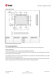


Table Of Contents
- Title
- Contents
- 1 Integration manual structure
- 2 System description
- 3 Receiver functionality
- 3.1 Receiver configuration
- 3.1.1 Changing the receiver configuration
- 3.1.2 Default GNSS configuration
- 3.1.3 Default interface settings
- 3.1.4 Basic receiver configuration
- 3.1.5 Differential timing mode configuration
- 3.1.6 Legacy configuration interface compatibility
- 3.1.7 Navigation configuration
- 3.2 Geofencing
- 3.3 Logging
- 3.4 Communication interfaces
- 3.5 Predefined PIOs
- 3.6 Antenna supervisor
- 3.7 Multiple GNSS assistance (MGA)
- 3.8 Clocks and time
- 3.9 Timing functionality
- 3.10 Security
- 3.11 u-blox protocol feature descriptions
- 3.12 Forcing a receiver reset
- 3.13 Firmware upload
- 3.1 Receiver configuration
- 4 Design
- 5 Product handling
- Appendix
- Related documents
- Revision history
- Contact

ZED-F9T-Integration manual
4.7.3.2 Paste mask
Figure 41: ZED-F9T suggested paste mask
4.7.4 Layout guidance
The presented layout guidance reduces the risk of performance issues at design level.
4.7.4.1 RF In trace
The RF in trace has to work in the combined GNSS signal bands.
For FR-4 PCB material with a dielectric permittivity of for example 4.7, the trace width for the 50 Ω
line impedance can be calculated.
A grounded co-planar RF trace is recommended as it provides the maximum shielding from noise
with adequate vias to the ground layer.
The RF trace must be shielded by vias to ground along the entire length of the trace and the ZED-
F9T RF_IN pad should be surrounded by vias as shown in the figure below.
UBX-19005590 - R05
4 Design Page 74 of 87
C1-Public Early production information