
Manual

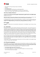

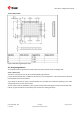


Table Of Contents
- Title
- Contents
- 1 Integration manual structure
- 2 System description
- 3 Receiver functionality
- 3.1 Receiver configuration
- 3.1.1 Changing the receiver configuration
- 3.1.2 Default GNSS configuration
- 3.1.3 Default interface settings
- 3.1.4 Basic receiver configuration
- 3.1.5 Differential timing mode configuration
- 3.1.6 Legacy configuration interface compatibility
- 3.1.7 Navigation configuration
- 3.2 Geofencing
- 3.3 Logging
- 3.4 Communication interfaces
- 3.5 Predefined PIOs
- 3.6 Antenna supervisor
- 3.7 Multiple GNSS assistance (MGA)
- 3.8 Clocks and time
- 3.9 Timing functionality
- 3.10 Security
- 3.11 u-blox protocol feature descriptions
- 3.12 Forcing a receiver reset
- 3.13 Firmware upload
- 3.1 Receiver configuration
- 4 Design
- 5 Product handling
- Appendix
- Related documents
- Revision history
- Contact

ZED-F9T-Integration manual
High temperature drift and air vents can affect the GNSS performance. For best
performance, avoid high temperature drift and air vents near the receiver.
4.7.3 Package footprint, copper and paste mask
Copper and solder mask dimensioning recommendations for the ZED-F9T module packages are
provided in this section.
These are recommendations only and not specifications. The exact copper, solder and paste
mask geometries, distances, stencil thickness and solder paste volumes must be adapted
to the specific production processes (e.g. soldering etc.) of the customer.
Refer to the ZED-F9T Data sheet [1] for the mechanical dimensions.
4.7.3.1 Footprint
Figure 40: ZED-F9T suggested footprint (i.e. copper mask)
UBX-19005590 - R05
4 Design Page 73 of 87
C1-Public Early production information