
Manual
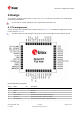


Table Of Contents
- Title
- Contents
- 1 Integration manual structure
- 2 System description
- 3 Receiver functionality
- 3.1 Receiver configuration
- 3.1.1 Changing the receiver configuration
- 3.1.2 Default GNSS configuration
- 3.1.3 Default interface settings
- 3.1.4 Basic receiver configuration
- 3.1.5 Differential timing mode configuration
- 3.1.6 Legacy configuration interface compatibility
- 3.1.7 Navigation configuration
- 3.2 Geofencing
- 3.3 Logging
- 3.4 Communication interfaces
- 3.5 Predefined PIOs
- 3.6 Antenna supervisor
- 3.7 Multiple GNSS assistance (MGA)
- 3.8 Clocks and time
- 3.9 Timing functionality
- 3.10 Security
- 3.11 u-blox protocol feature descriptions
- 3.12 Forcing a receiver reset
- 3.13 Firmware upload
- 3.1 Receiver configuration
- 4 Design
- 5 Product handling
- Appendix
- Related documents
- Revision history
- Contact

ZED-F9T-Integration manual
If customers do not want to make use of the antenna supervisor function the filtered VCC_RF supply
voltage output can supply the antenna if the supply voltage of the ZED-F9T module matches the
antenna working voltage (e.g. 3.0 V).
A series current limiting resistor is required to prevent short circuits destroying the bias-t
inductor.
The bias-t inductor must be chosen for multi-band operation, a value of 47 nH ±5% is
recommended for the recommended Murata L part. It has a self-resonance frequency of 1
GHz and a high impedance (> 500 Ω) at L band frequencies.
The recommended bias-t inductor (Murata LQG15HS47NJ02) has a maximum current capacity of
300 mA. Hence the current is limited to 70 mA at 3.3V using an active limiter in the recommended
circuit shown in Figure 35 below. A 10 Ω resistor (R2) is provided to measure the current. This resistor
power rating must be chosen to ensure reliability in the chosen circuit design.
Figure 34: ZED-F9T antenna bias inductor impedance
A recommended circuit design for an active antenna bias is shown below. This example shows an
external voltage of 3.3 V with current limiting as described above. An ESD protection diode should
also be connected to the input as shown.
UBX-19005590 - R05
4 Design Page 67 of 87
C1-Public Early production information