
Manual

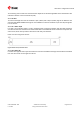


Table Of Contents
- Title
- Contents
- 1 Integration manual structure
- 2 System description
- 3 Receiver functionality
- 3.1 Receiver configuration
- 3.1.1 Changing the receiver configuration
- 3.1.2 Default GNSS configuration
- 3.1.3 Default interface settings
- 3.1.4 Basic receiver configuration
- 3.1.5 Differential timing mode configuration
- 3.1.6 Legacy configuration interface compatibility
- 3.1.7 Navigation configuration
- 3.2 Geofencing
- 3.3 Logging
- 3.4 Communication interfaces
- 3.5 Predefined PIOs
- 3.6 Antenna supervisor
- 3.7 Multiple GNSS assistance (MGA)
- 3.8 Clocks and time
- 3.9 Timing functionality
- 3.10 Security
- 3.11 u-blox protocol feature descriptions
- 3.12 Forcing a receiver reset
- 3.13 Firmware upload
- 3.1 Receiver configuration
- 4 Design
- 5 Product handling
- Appendix
- Related documents
- Revision history
- Contact

ZED-F9T-Integration manual
Figure 24: GPS L2C subframe words
3.11.1.3 GLONASS
For GLONASS L1OF and L2OF signals, the UBX-RXM-SFRBX message contains a string content
within the frame structure as described in the GLONASS ICD. This string comprises 85 data bits
which are reported over three 32-bit words in the message. Data bits 1 to 8 are always a hamming
code, whilst bits 81 to 84 are a string number and bit 85 is the idle chip, which should always have a
value of zero. The meaning of other bits varies with string and frame number.
The fourth and final 32-bit word in the UBX-RXM-SFRBX message contains frame and superframe
numbers (where available). These values are not actually transmitted by the satellites, but are
deduced by the receiver and are included to aid decoding of the transmitted data. However, the
receiver does not always know these values, in which case a value of zero is reported.
The four words are arranged as follows:
UBX-19005590 - R05
3 Receiver functionality Page 54 of 87
C1-Public Early production information