
Manual


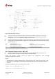


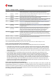
Table Of Contents
- Title
- Contents
- 1 Integration manual structure
- 2 System description
- 3 Receiver functionality
- 3.1 Receiver configuration
- 3.1.1 Changing the receiver configuration
- 3.1.2 Default GNSS configuration
- 3.1.3 Default interface settings
- 3.1.4 Basic receiver configuration
- 3.1.5 Differential timing mode configuration
- 3.1.6 Legacy configuration interface compatibility
- 3.1.7 Navigation configuration
- 3.2 Geofencing
- 3.3 Logging
- 3.4 Communication interfaces
- 3.5 Predefined PIOs
- 3.6 Antenna supervisor
- 3.7 Multiple GNSS assistance (MGA)
- 3.8 Clocks and time
- 3.9 Timing functionality
- 3.10 Security
- 3.11 u-blox protocol feature descriptions
- 3.12 Forcing a receiver reset
- 3.13 Firmware upload
- 3.1 Receiver configuration
- 4 Design
- 5 Product handling
- Appendix
- Related documents
- Revision history
- Contact

ZED-F9T-Integration manual
Figure 17: ZED-F9T antenna supervisor
The bias-t inductor must be chosen for multi-band operation; a value of 47 nH ±5% is
required for our recommended Murata part, with the current limited below its 300 mA
rating. See Antenna bias section for additional information.
Circuit shows buffer [U4]. Buffer is not strictly necessary when supplied from VCC. It is only
required when supplying antenna voltage that is not obtained from or controlled by module
VCC or VCC_RF .
Part Recommendation Comment
L1 Murata LQG15HS47NJ02/47N 300mA and >500 Ω at L band frequencies
C2 Murata GRM033R71C103KE14 CAP CER X7R 0402 10N 10% 16V
TYCO, 0.25PF, PESD0402-140 -55/+125C ESD protection diode on RF trace
Table 19: Recommended components for antenna supervisor
3.6.1 Antenna voltage control - ANT_OFF
Antenna status (as reported in UBX-MON-RF and UBX-INF-NOTICE messages) is not
reported unless the antenna voltage control has been enabled.
Enable the antenna voltage control by setting the configuration item CFG-HW-
ANT_CFG_VOLTCTRL to true (1).
Result:
• UBX-MON-RF in u-center "Message View": Antenna status = OK. Antenna power status = ON
• ANT_OFF pin = active high to turn antenna off therefore the pin is low to enable an external
antenna.
Start-up message at power up if configuration stored:
$GNTXT,01,01,02,ANTSUPERV=AC *00
$GNTXT,01,01,02,ANTSTATUS=INIT*3B
UBX-19005590 - R05
3 Receiver functionality Page 34 of 87
C1-Public Early production information