
Manual


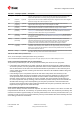
Table Of Contents
- Title
- Contents
- 1 Integration manual structure
- 2 System description
- 3 Receiver functionality
- 3.1 Receiver configuration
- 3.1.1 Changing the receiver configuration
- 3.1.2 Default GNSS configuration
- 3.1.3 Default interface settings
- 3.1.4 Basic receiver configuration
- 3.1.5 Differential timing mode configuration
- 3.1.6 Legacy configuration interface compatibility
- 3.1.7 Navigation configuration
- 3.2 Geofencing
- 3.3 Logging
- 3.4 Communication interfaces
- 3.5 Predefined PIOs
- 3.6 Antenna supervisor
- 3.7 Multiple GNSS assistance (MGA)
- 3.8 Clocks and time
- 3.9 Timing functionality
- 3.10 Security
- 3.11 u-blox protocol feature descriptions
- 3.12 Forcing a receiver reset
- 3.13 Firmware upload
- 3.1 Receiver configuration
- 4 Design
- 5 Product handling
- Appendix
- Related documents
- Revision history
- Contact

ZED-F9T-Integration manual
It is recommended to have the possibility to pull the SAFEBOOT_N pin low in the application. This
can be provided using an externally connected test point or a host I/O port.
3.5.4 TIMEPULSE
The ZED-F9T provides time pulse signals on the TIMEPULSE and TIMEPULSE2 pins.
More information about the time pulse feature and its configuration can be found in the Time pulse
section.
3.5.5 EXTINT
EXTINT, EXTINT2 are external interrupt pins with fixed input voltage thresholds with respect to
VCC. They can be used for functions such as accurate external frequency aiding and on/off control.
The external frequency aiding can be used to calibrate the clock. This enables faster fix of satellite
signals (UBX-MGA-INI-FREQ or UBX-MGA-INI-TIME_XXX) and can be used during normal operation
or during the production test. Another possibility to use the extint feature, is to wake-up the receiver
after putting it into backup mode; this can be set up with UBX-RXM-PMREQ. Leave open if unused,
this function is disabled by default.
3.6 Antenna supervisor
An active antenna supervisor provides the means to check the antenna for open and short circuits
and to shut off the antenna supply if a short circuit is detected. Once enabled, the active antenna
supervisor produces status messages, reporting in NMEA and/or UBX protocol.
The antenna supervisor can be configured through the CFG-HW-ANT_* configuration items. The
current configuration of the active antenna supervisor can also be checked by polling the related
CFG-HW_ANT_* configuration items.
The current active antenna status can be determined by polling the UBX-MON-RF message. If an
antenna is connected, the initial state after power-up is “Active Antenna OK" in the UBX-MON-RF
message in the u-center "Message View".
An active antenna supervisor circuit is connected to the ANT_DET, ANT_OFF, ANT_SHORT_N
pins. For an example the open circuit detection circuit using ANT_DET, "high" = Antenna detected
(antenna consumes current); "low" = Antenna not detected (no current drawn).
The following schematic details the required circuit and the sections following it explain how to
enable and monitor each feature:
UBX-19005590 - R05
3 Receiver functionality Page 33 of 87
C1-Public Early production information