
Manual
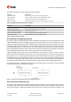


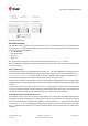
Table Of Contents
- Title
- Contents
- 1 Integration manual structure
- 2 System description
- 3 Receiver functionality
- 3.1 Receiver configuration
- 3.1.1 Changing the receiver configuration
- 3.1.2 Default GNSS configuration
- 3.1.3 Default interface settings
- 3.1.4 Basic receiver configuration
- 3.1.5 Differential timing mode configuration
- 3.1.6 Legacy configuration interface compatibility
- 3.1.7 Navigation configuration
- 3.2 Geofencing
- 3.3 Logging
- 3.4 Communication interfaces
- 3.5 Predefined PIOs
- 3.6 Antenna supervisor
- 3.7 Multiple GNSS assistance (MGA)
- 3.8 Clocks and time
- 3.9 Timing functionality
- 3.10 Security
- 3.11 u-blox protocol feature descriptions
- 3.12 Forcing a receiver reset
- 3.13 Firmware upload
- 3.1 Receiver configuration
- 4 Design
- 5 Product handling
- Appendix
- Related documents
- Revision history
- Contact

ZED-F9T-Integration manual
Figure 11: I2C register layout
3.4.2.2 Read access types
There are two I2C read transfer forms:
• The "random access" form: includes a slave register address and allows any register to be read.
• The "current address" form: omits the register address.
Figure 12 shows the format of the first one, the "random access" form of the request. Following
the start condition from the master, the 7-bit device address and the RW bit (which is a logic low
for write access) are clocked onto the bus by the master transmitter. The receiver answers with an
acknowledge (logic low) to indicate that it recognizes the address.
Next, the 8-bit address of the register to be read must be written to the bus. Following the receiver's
acknowledgment, the master again triggers a start condition and writes the device address, but this
time the RW bit is a logic high to initiate the read access. Now, the master can read 1 to N bytes
from the receiver, generating a not-acknowledge and a stop condition after the last byte being read.
UBX-19005590 - R05
3 Receiver functionality Page 28 of 87
C1-Public Early production information