
Manual


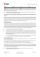


Table Of Contents
- Title
- Contents
- 1 Integration manual structure
- 2 System description
- 3 Receiver functionality
- 3.1 Receiver configuration
- 3.1.1 Changing the receiver configuration
- 3.1.2 Default GNSS configuration
- 3.1.3 Default interface settings
- 3.1.4 Basic receiver configuration
- 3.1.5 Differential timing mode configuration
- 3.1.6 Legacy configuration interface compatibility
- 3.1.7 Navigation configuration
- 3.2 Geofencing
- 3.3 Logging
- 3.4 Communication interfaces
- 3.5 Predefined PIOs
- 3.6 Antenna supervisor
- 3.7 Multiple GNSS assistance (MGA)
- 3.8 Clocks and time
- 3.9 Timing functionality
- 3.10 Security
- 3.11 u-blox protocol feature descriptions
- 3.12 Forcing a receiver reset
- 3.13 Firmware upload
- 3.1 Receiver configuration
- 4 Design
- 5 Product handling
- Appendix
- Related documents
- Revision history
- Contact

ZED-F9T-Integration manual
The geofencing feature allows for the configuration of up to four circular areas (geofences) on the
Earth's surface. The receiver will then evaluate for each of these areas whether the current position
lies within the area or not and signal the state via UBX messaging and PIO toggling.
3.2.2 Interface
Geofencing can be configured using the CFG-GEOFENCE-* configuration group. The geofence
evaluation is active whenever there is at least one geofence configured.
The current state of each geofence plus the combined state is output in UBX-NAV-GEOFENCE with
every navigation epoch.
3.2.3 Geofence state evaluation
With every navigation epoch the receiver will evaluate the current solution's position versus the
configured geofences. There are three possible outcomes for each geofence:
•
Inside - The position is inside the geofence with the configured confidence level
•
Outside - The position lies outside of the geofence with the configured confidence level
•
Unknown - There is no valid position solution or the position uncertainty does not allow for
unambiguous state evaluation
The position solution uncertainty (standard deviation) is multiplied with the configured confidence
sigma level number and taken into account when evaluating the geofence state (red circle in figure
below).
Figure 6: Geofence states
The combined state for all geofences is evaluated as the combination (Union) of all geofences:
•
Inside - The position lies inside of at least one geofence
•
Outside - The position lies outside of all geofences
•
Unknown - All remaining states
3.2.4 Using a PIO for geofence state output
This feature can be used for example for waking up a sleeping host when a defined geofence
condition is reached. The receiver will toggle the assigned pin according to the combined geofence
state. Due to hardware restrictions, the geofence unknown state is not configurable and is always
represented as HIGH. If the receiver is in the software backup mode or in the reset state, the pin
will go to HIGH accordingly. The meaning of the LOW state can be configured using the CFG-
GEOFENCE-PINPOL configuration item.
3.3 Logging
3.3.1 Introduction
The logging feature allows position fixes and arbitrary byte strings from the host to be logged in the
receiver's flash memory. Logging of position fixes happens independently of the host system, and
can continue while the host is powered down.
UBX-19005590 - R05
3 Receiver functionality Page 21 of 87
C1-Public Early production information