
Manual


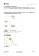
Table Of Contents
- Title
- Contents
- 1 Integration manual structure
- 2 System description
- 3 Receiver functionality
- 3.1 Receiver configuration
- 3.1.1 Changing the receiver configuration
- 3.1.2 Default GNSS configuration
- 3.1.3 Default interface settings
- 3.1.4 Basic receiver configuration
- 3.1.5 Differential timing mode configuration
- 3.1.6 Legacy configuration interface compatibility
- 3.1.7 Navigation configuration
- 3.2 Geofencing
- 3.3 Logging
- 3.4 Communication interfaces
- 3.5 Predefined PIOs
- 3.6 Antenna supervisor
- 3.7 Multiple GNSS assistance (MGA)
- 3.8 Clocks and time
- 3.9 Timing functionality
- 3.10 Security
- 3.11 u-blox protocol feature descriptions
- 3.12 Forcing a receiver reset
- 3.13 Firmware upload
- 3.1 Receiver configuration
- 4 Design
- 5 Product handling
- Appendix
- Related documents
- Revision history
- Contact

ZED-F9T-Integration manual
Interface Configuration groups
I2C CFG-I2C-*, CFG-I2CINPROT-*, CFG-I2COUTPROT-*
SPI CFG-SPI-*, CFG-SPIINPROT-*, CFG-SPIOUTPROT-*
Table 2: Interface configurations
3.1.4.2 Message output configuration
The rate of the supported output messages is configurable.
If the rate configuration value is zero, then the corresponding message will not be output. Values
greater than zero indicate how often the message is output.
For periodic output messages the rate relates to the event the message is related to. For example,
the UBX-NAV-PVT (navigation, position, velocity and time solution) is related to the navigation
epoch. If the rate of this message is set to one (1), it will be output for every navigation epoch. If the
rate is set to two (2), it will be output every other navigation epoch. The rates of the output messages
are individually configurable per communication interface. See the CFG-MSGOUT-* configuration
group.
Some messages, such as UBX-MON-VER, are non-periodic and will only be output as an answer to
a poll request.
The UBX-INF-* and NMEA-Standard-TXT information messages are non-periodic output messages
that do not have a message rate configuration. Instead they can be enabled for each communication
interface via the CFG-INFMSG-* configuration group.
All message output is additionally subject to the protocol configuration of the
communication interfaces. Messages of a given protocol will not be output until the protocol
is enabled for output on the interface (see the Communication interface configuration).
3.1.4.3 GNSS signal configuration
The GNSS constellations and bands are configurable with configuration keys from configuration
group CFG-SIGNAL-*. Each GNSS constellation can be enabled or disabled independently. A GNSS
constellation is considered to be enabled when the constellation enable key is set and at least one
of the constellation's band keys is enabled.
3.1.4.4 Antenna supervisor configuration
This section describes the antenna supervisor configuration, its use and restrictions.
The antenna supervisor is used to control an active antenna. The configuration of the antenna
supervisor allows the following:
• Control voltage supply to the antenna, which allows the antenna supervisor to cut power to the
antenna in the event of a short circuit or optimize power to the antenna in power save mode
• Detect a short circuit in the antenna and auto recover the antenna supply in such an event
• Detect an open antenna, which can be used to indicate if the antenna has been disconnected
See the table below for a description of the configuration items related to the antenna supervisor
operation.
Configuration item Description Comments
CFG-HW-ANT_CFG_VOLTCTRL Enable active antenna voltage control
CFG-HW-ANT_CFG_SHORTDET Enable short circuit detection
CFG-HW-ANT_CFG_SHORTDET_POL Short antenna detection polarity Set to 1 if the required logic polarity is
active-low (default)
CFG-HW-ANT_CFG_OPENDET Enable open circuit detection
UBX-19005590 - R05
3 Receiver functionality Page 11 of 87
C1-Public Early production information