
Data Sheet

SAM-M8Q - Data Sheet
UBX-16012619 - R04 Production Information Electrical specification
Page 17 of 25
Input pin voltage range
Vin
0
VCC_IO + 0.5
V
Digital IO Pin Low level input voltage
Vil
0
0.2*VCC_IO
V
Digital IO Pin High level input voltage
Vih
0.7*VCC_IO
VCC_IO + 0.5
V
Digital IO Pin Low level output voltage
Vol
0.4
V
Iol = 4 mA
Digital IO Pin High level output voltage
Voh
VCC_IO – 0.4
V
Ioh = 4 mA
Pull-up resistor at RESET_N (internal)
Rpu
11
k
Operating temperature
Topr
–40
85
°C
Table 7: Operating conditions
Operation beyond the specified operating conditions can affect device reliability.
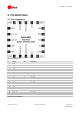
4.3 Indicative current requirements
Table 8 lists examples of the total system supply current for a possible application.
Values in Table 8 are only provided for customer information as an example of typical power
requirements. Values are characterized on samples; actual power requirements can vary depending on the
firmware version used, external circuitry, number of SVs tracked, signal strength, type of start as well as
time, duration and conditions of tests.
Parameter
Symbol
Typ
GPS & GLONASS
Typ
GPS
Max
Units
Condition
Max. supply current
11
Iccp
67
mA
Average supply current
12, 13
Icc Acquisition
14
32
25
mA
Estimated at 3 V
Icc Tracking
(Continuous mode)
29
23
mA
Estimated at 3 V
Icc Tracking
(Power Save mode / 1 Hz)
9.5
9.5
mA
Estimated at 3 V
Table 8: Indicative power requirements at 3.0 V
For more information about power requirements, see the SAM-M8Q Hardware Integration Manual [1].
For more information on how to noticeably reduce current consumption, see the Power Management
Application Note [5].
11
Use this figure to dimension maximum current capability of power supply. Measurement of this parameter with 1 Hz bandwidth.
12
Use this figure to determine required battery capacity.
13
Good sky view. VCC = 3.0 V
14
Average current from start-up until the first fix.