SAM-M8Q Easy-to-use u-blox M8 GNSS antenna module Hardware Integration Manual Abstract This document describes the hardware features and specifications of the SAM-M8Q patch antenna module, which features the u-blox M8 concurrent GNSS engine with reception of GPS, GLONASS, Galileo and QZSS signals. Top and bottom view www.u-blox.
SAM-M8Q - Hardware Integration Manual Document Information Title SAM-M8Q Subtitle Easy-to-use u-blox M8 GNSS antenna module Document type Hardware Integration Manual Document number UBX-16018358 Revision and Date R05 Document Status Production Information 24-Oct-2017 Document status explanation Objective Specification Document contains target values. Revised and supplementary data will be published later. Advance Information Document contains data based on early testing.
SAM-M8Q - Hardware Integration Manual Preface u-blox Technical Documentation As part of our commitment to customer support, u-blox maintains an extensive volume of technical documentation for our products. In addition to our product-specific technical data sheets, the following manuals are available to assist u-blox customers in product design and development.
SAM-M8Q - Hardware Integration Manual Contents Preface ................................................................................................................................ 3 Contents.............................................................................................................................. 4 1 Hardware description .................................................................................................. 5 1.1 Overview .................................................
SAM-M8Q - Hardware Integration Manual 1 Hardware description 1.1 Overview The SAM‑M8Q module is a concurrent GNSS patch antenna module featuring the high performance u-blox M8 GNSS engine with reception of GPS, GLONASS, Galileo and QZSS signals. Available in an LGA package, it is easy to integrate and combines exceptional positioning performance with highly flexible power, design, and connectivity options.
SAM-M8Q - Hardware Integration Manual Avoid high resistance on the V_BCKP line: During the switch from main supply to backup supply, a short current adjustment peak can cause high voltage drop on the pin with possible malfunctions. If no backup supply voltage is available, connect the V_BCKP pin to VCC_IO. As long a supply is connected to VCC_IO of SAM‑M8Q antenna module, the backup battery is disconnected from the RTC and the BBR to avoid unnecessary battery drain (see Figure 1).
SAM-M8Q - Hardware Integration Manual 1.5 I/O pins 1.5.1 RESET_N: Reset Driving RESET_N low activates a hardware reset of the system. Use this pin only to reset the module. Do not use RESET_N to turn the module on and off, since the reset state increases power consumption. The SAM-M8Q RESET_N pin is for input only. The RTC time is also reset (but not BBR). Means the Hotstart performance will be degraded after a reset.
SAM-M8Q - Hardware Integration Manual 1.6 Electromagnetic interference on I/O lines Any I/O signal line with a length greater than approximately 3 mm can act as an antenna and may pick up arbitrary RF signals transferring them as noise into the GNSS receiver. This specifically applies to unshielded lines, in which the corresponding GND layer is remote or missing entirely, and lines close to the edges of the printed circuit board.
SAM-M8Q - Hardware Integration Manual 2 Design 2.1 Pin description Function PIN No Power VCC GND UART DDC System I/O Description Remarks 17 Main supply Provide clean and stable supply (low impedance, < 0.2 Ohms). 1, 4, 5, 6, 10, 11, 15, 16, 20 Ground Assure a good GND connection to all GND pins of the module. VCC_IO 2 VCC_IO IO supply voltage. Must be always supplied.
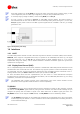
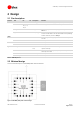
SAM-M8Q - Hardware Integration Manual 2.3 Footprint and paste mask The suggested solder mask openings are the same as the pad layout. Be sure to comply with special PCB layout design rules to ensure proper embedded antenna operation when the customer PCB is used as part of antenna. This requires solid ground plane around the module, see the section 2.60 for PCB layout suggestions. Footprint Figure 4: SAM-M8Q footprint Symbol Typ [mm] A 15.50 B 7.60 C 3.80 D R1.00 E 11.00 F 6.30 H 1.
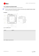
SAM-M8Q - Hardware Integration Manual Paste mask Stencil thickness: 120 µm Orange: Pad Grey: stencil opening Figure 5: Suggested pad layout and occupied area, top view Figure 6: Paste mask detail for each pad 2.4 Antenna SAM-M8Q GNSS patch antenna module is designed with an integrated GPS/Galileo/GLONASS patch antenna.
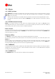
SAM-M8Q - Hardware Integration Manual 2.5 Embedded antenna operation The embedded GPS/Galileo/GLONASS patch antenna provides optimal performance in the middle of a 50 x 50 mm ground plane. Figure 7: 1.575 GHz typical free space radiation patterns Tall nearby components (h > 3 mm) should be placed at least 10 mm away from the SAM-M8Q module. An enclosure or plastic cover should have a minimum distance of 5 mm to the antenna.
SAM-M8Q - Hardware Integration Manual 2.6 PCB layout suggestion For good performance, it is essential to have a proper layout and placement. Figure 8: Layout recommendation (top layer) SAM‑M8Q GNSS patch antenna module is intended to be placed in the middle of 50 x 50 mm GND size board, but a larger or smaller ground plane can be used. When using smaller than 40 x 40 mm ground plane, the performance may get decreased significantly.
SAM-M8Q - Hardware Integration Manual 3 Product handling 3.1 Packaging, shipping, storage and moisture preconditioning For information pertaining to reels and tapes, Moisture Sensitivity levels (MSL), shipment and storage information, as well as drying for preconditioning see the SAM-M8Q Data Sheet [1]. Population of Modules When populating the modules, make sure that the pick and place machine is aligned to the copper pins of the module and not to the module edge. 3.
SAM-M8Q - Hardware Integration Manual Cooling phase A controlled cooling avoids negative metallurgical effects of the solder (becoming more brittle) and possible mechanical tensions in the products. Controlled cooling helps to achieve bright solder fillets with a good shape and low contact angle. Temperature fall rate: max 4 °C/s To avoid falling off, the SAM‑M8Q antenna module should be placed on the topside of the motherboard during soldering.
SAM-M8Q - Hardware Integration Manual Repeated reflow soldering Only single reflow soldering process is recommended for boards populated with SAM‑M8Q GNSS patch antenna module. The SAM‑M8Q antenna module should not be submitted to two reflow cycles on a board populated with components on both sides in order to avoid upside down orientation during the second reflow cycle. In this case, the modules should always be placed on the side of the board that is submitted into the last reflow cycle.
SAM-M8Q - Hardware Integration Manual 3.3 EOS/ESD/EMI precautions When integrating GNSS positioning modules into wireless systems, careful consideration must be given to electromagnetic and voltage susceptibility issues. Wireless systems include components that can produce Electrical Overstress (EOS) and Electro-Magnetic Interference (EMI).
SAM-M8Q - Hardware Integration Manual GNSS positioning modules are sensitive to Electrostatic Discharge (ESD). Special precautions are required when handling. Electrical overstress (EOS) Electrical overstress (EOS) usually describes situations when the maximum input power exceeds the maximum specified ratings. EOS failure can happen if RF emitters are close to a GNSS receiver or its antenna. EOS causes damage to the chip structures.
SAM-M8Q - Hardware Integration Manual 3.4 Applications with cellular modules GSM terminals transmit power levels up to 2 W (+33 dBm) peak, 3G and LTE up to 250 mW continuous. Consult the corresponding product data sheet in Related documents for the absolute maximum power input at the GNSS receiver. See the GPS Implementation and Aiding Features in u-blox wireless modules [7].
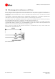
SAM-M8Q - Hardware Integration Manual Measures against in-band interference include: Maintaining a good grounding concept in the design Shielding Layout optimization Filtering Placement of the GNSS antenna Adding a CDMA, cellular, WCDMA band pass filter before handset antenna Out-band interference Out-band interference is caused by signal frequencies that are different from the GNSS carrier (see Figure 12).
SAM-M8Q - Hardware Integration Manual Appendix A Glossary Abbreviation Definition ANSI American National Standards Institute CDMA Code Division Multiple Access EMC Electromagnetic compatibility EMI Electromagnetic interference EOS Electrical Overstress EPA Electrostatic Protective Area ESD Electrostatic discharge Galileo European navigation system GLONASS Russian satellite system GND Ground GNSS Global Navigation Satellite System GPS Global Positioning System GSM Global System fo
SAM-M8Q - Hardware Integration Manual Related documents [1] [2] SAM-M8Q Data Sheet, Docu. No. UBX-16012619 u-blox 8 / u-blox M8 Receiver Description Including Protocol Specification (Public version), Docu. No. UBX-13003221 [3] [4] GNSS FW3.01 Release Notes (Public version), Docu. No. UBX-16000319 GPS Antenna Application Note, Docu. No. GPS-X-08014 [5] GPS Compendium, Docu No. GPS-X-02007 [6] I2C-bus specification, Rev. 6 — 4 April 2014, http://www.nxp.com/documents/user_manual/UM10204.
SAM-M8Q - Hardware Integration Manual Contact For complete contact information, visit us at www.u-blox.com u-blox Offices North, Central and South America u-blox America, Inc. Phone: +1 703 483 3180 E-mail: info_us@u-blox.com Regional Office West Coast: Phone: +1 408 573 3640 E-mail: info_us@u-blox.com Technical Support: Phone: E-mail: Headquarters Europe, Middle East, Africa u-blox AG Phone: E-mail: Support: +41 44 722 74 44 info@u-blox.com support@u-blox.