
Data Sheet

ZOE-M8 - Data Sheet
UBX-16008094 - R07 Production Information Electrical specification
Page 21 of 29
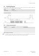
4.2 SPI timing diagrams
In order to avoid incorrect operation of the SPI, the user needs to comply with certain timing conditions. The
following signals need to be considered for timing constraints:
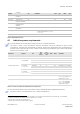
Symbol Description
SPI CS_N (SS_N) Slave select signal
SPI CLK (SCK) Slave clock signal
Table 14: Symbol description
Figure 4: SPI timing diagram
4.2.1 Timing recommendations
The recommendations below are based on a firmware running from SQI flash memory.
Parameter Description Recommendation
t
INIT
Minimum Initialization Time 10 us
t
DES
Deselect Time 1 ms
t
bit
Minimum bit time 180 ns (5.5 MHz max bit frequency)
t
byte
Minimum byte period
8 µs (125 kHz max byte frequency)
Table 15: SPI timing recommendations
The values in the above table result from the requirement of an error-free transmission. By allowing just a
few errors and disabling the glitch filter, the bit rate can be increased considerably.