
Data Sheet

ZOE-M8 - Data Sheet
UBX-16008094 - R07 Production Information Electrical specification
Page 20 of 29
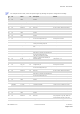
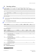
Symbol
Parameter
SiP Condition Min. Typ. Max. Unit
RTC_Fxtal RTC crystal resonant
frequency
All 32768 Hz
RTC_T_start RTC startup time All 0.2 0.35 0.9 sec
RTC_Amp 32768 Hz OSC
oscillation amplitude
All 50 350 mVpp
RTC_ESR 32768 Hz Xtal
equivalent series
resistance
All
100
kΩ
RTC_CL RTC integrated load
capacitance
All
ESR = 80 kΩ
4 7 12 pF
DCDC_eff DC/DC efficiency ZOE-M8Q 4 3.3 V @ input, 4 mA – 80 mA,
External components: L = 2.2 µH,
C = 4.7 µF
85 %
V_DCDC_out DC/DC output voltage ZOE-M8Q DC/DC enabled 1.4 V
Table 12: Baseband parameters
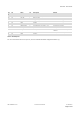
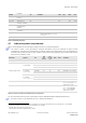
4.1 Indicative power requirements
Table 13 lists examples of the total system supply current for a possible application.
The values in Table 13 are provided for customer information only as an example of typical current
requirements. The values are characterized on samples; actual power requirements can vary depending on
firmware version used, external circuitry, number of SVs tracked, signal strength, type of start as well as time,
duration and conditions of test.
Parameter Symbol SiP
Typ
GPS &
GLONASS
Typ
GPS / QZSS
/ SBAS
Max Units Condition
Max. supply current
14
Iccp All 67 mA
Average supply current
15
Icc Acquisition
16
ZOE-M8G 45 34.5 mA Estimated at 1.8 V
ZOE-M8Q 28 22 mA Estimated at 3 V w/ DC/DC
ZOE-M8Q 45 34.5 mA Estimated at 3 V w/o DC/DC
Icc Tracking
(Continuous mode)
ZOE-M8G 40 32.5 mA Estimated at 1.8 V
ZOE-M8Q 25 21 mA Estimated at 3 V w/ DC/DC
ZOE-M8Q 40 32.5 mA Estimated at 3 V w/o DC/DC
Icc Tracking
(Power Save mode / 1 Hz)
ZOE-M8G 12.5 11.5 mA Estimated at 1.8 V
ZOE-M8Q 9.0 8.5 mA Estimated at 3 V w/ DC/DC
ZOE-M8Q 12.5 11.5 mA Estimated at 3 V w/o DC/DC
Backup battery current
17
I_BCKP
All 15 µA HW Backup mode,
VCC = 0 V, V_BCKP = 3 V
using the RTC crystal
SW Backup current
I_SWBCKP
All 20 µA SW Backup mode,
VCC = 1.8 V (ZOE-M8G)
VCC = 3.0 V (ZOE-M8Q)
using the RTC crystal
Table 13: Currents to calculate the indicative power requirements
For more information about power requirements, see the ZOE-M8 Hardware Integration Manual [1].
All values in Table 13 are measured at +25 °C ambient temperature.
14
Use this figure to dimension maximum current capability of power supply. Measurement of this parameter with 1 Hz bandwidth.
15
Simulated constellation of 8 satellites is used. All signals are at -130 dBm.
16
Average current from start-up until the first fix.
17
Use this figure to determine required battery capacity.