
Data Sheet

ZOE-M8 - Data Sheet
UBX-16008094 - R07 Production Information Electrical specification
Page 18 of 29
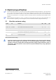
3 Electrical specification
The limiting values given are in accordance with the Absolute Maximum Rating System (IEC 134). Stress above
one or more of the limiting values may cause permanent damage to the device. These are stress ratings only,
and operation of the device at these or at any other conditions above those given in the Characteristics
sections of the specification is not implied. Exposure to limiting values for extended periods may affect device
reliability.
Where application information is given, it is advisory only and does not form part of the specification. For
more information regarding power management, see the ZOE-M8 Hardware Integration Manual [1].
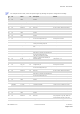
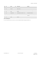
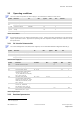
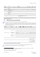
3.1 Absolute maximum rating
Symbol SiP Parameter Min Max Unit
VCC All Supply voltage –0.5 3.6 V
V_CORE ZOE-M8Q Core supply voltage –0.5 3.6 V
V_DCDC_OUT ZOE-M8Q Output voltage of the internal DC/DC converter –0.5 3.6 V
V_BCKP All Supply voltage baseband backup core –0.5 3.6 V
Vi
RTC
All
Input voltage on RTC_I
–0.5
1.6
V
Vi
DIG
All Input voltage on Configurable Inputs , RESET_N if VCC < 3.1 V
Input voltage on Configurable Inputs , RESET_N if VCC > 3.1 V
–0.5 VCC+0.5
3.6
V
V
Prfin All RF Input power on RF_IN inband
11
0 dBm
All RF Input power on RF_IN outband
12
+15 dBm
Ptot All Total power dissipation 500 mW
Ts All Storage temperature –40 +85 °C
Table 8: Absolute maximum ratings
Stressing the device beyond the “Absolute Maximum Ratings” may cause permanent damage.
These are stress ratings only. The product is not protected against overvoltage or reversed
voltages. If necessary, voltage spikes exceeding the power supply voltage specification, given in
table above, must be limited to values within the specified boundaries by using appropriate
protection diodes.
11
Inband = 1525-1650 MHz
12
Outband = 777-915 MHz, 1710-2200 MHz