
Data Sheet

ZOE-M8 - Data Sheet
UBX-16008094 - R07 Production Information Functional description
Page 12 of 29
The ZOE-M8 SiPs make use of a UART interface, which can be used for communication to a host. It supports
configurable baud rates. For supported transfer rates, see the u-blox 8 / u-blox M8 Receiver Description Including
Protocol Specification [2].
Designs must allow access to the UART and the SAFEBOOT_N pin for future service, updates and
reconfiguration.
1.17.2 SPI
The SPI interface is designed to allow communication to a host CPU. The interface can be operated in slave mode
only. The maximum transfer rate using SPI is 125 kB/s and the maximum SPI clock frequency is 5.5 MHz. Note that
SPI is not available in the default configuration, because its pins are shared with the UART and DDC interfaces.
The SPI interface can be enabled by connecting D_SEL to ground (see section 1.17.5). In this case the DDC interface
for data communication is no longer available.
1.17.3 Display Data Channel (DDC)
An I
2
C compliant DDC interface is available for communication with an external host CPU or u-blox cellular module.
The interface can be operated in slave mode only. The DDC protocol and electrical interface are fully compatible
with Fast-Mode of the I
2
C industry standard. Since the maximum SCL clock frequency is 400 kHz, thus the
maximum transfer rate is 400 kb/s.
The DDC interface is I
2
C Fast Mode compliant. For timing parameters, consult the I
2
C standard.
The maximum bit rate is 400 kb/s. The interface stretches the clock when slowed down while serving
interrupts, so real bit rates may be slightly lower.
1.17.4 Serial Quad Interface (SQI)
An SQI is available in ZOE-M8 SiPs for connecting with an optional external flash memory. The flash memory is
required for firmware updates and for data logging. In addition, it can be used to store configurations and to save
AssistNow Offline and AssistNow Autonomous data.
For more information, see the ZOE-M8 Hardware Integration Manual [1].
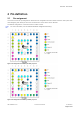
1.17.5 Interface selection (D_SEL)
At startup the D_SEL pin determines which data interfaces are used for communication. If D_SEL is set to logical
“1” or is not connected, UART and DDC become available. If D_SEL is set to logical “0”, i.e. connected to GND,
the ZOE-M8 SiPs can communicate to a host via SPI.
Pin #
(D_SEL)=”1”
(left open)
(D_SEL)=”0”
(connected to GND)
J5 UART TX SPI MISO
J4 UART RX SPI MOSI
B1 DDC SCL SPI CLK
A2 DDC SDA SPI CS_N
Table 5: Data interface selection by D_SEL
1.18 Configurable Input Output pins
Configuration settings can be modified for several Input/Output pins with either UBX configuration messages or
pin selection. This flexible configuration options allow the receivers to be optimally configured for specific
applications requirements. The modified settings remain either permanent or effective until power-down or reset
depending on the case. Customer can activate or remap the following pins on ZOE-M8 SiPs:
1. Selection of DDC, UART TX/RX pins interface or SPI using D_SEL pin. See section 1.17.5.
2. Selection of external interrupt pins. See section 1.14.
3. Configuration of Timepulse. See section 1.15.
For more information, see the ZOE-M8 Hardware Integration Manual [1].