ZOE-M8 Ultra-small u-blox M8 GNSS SiP modules Data Sheet Ultra-small GNSS SiP modules with superior performance • Ultra-small size SiP (System-in-Package) 4.5 mm x 4.5 mm x 1.0 mm • Fully integrated, complete solution, reducing design and test efforts • Ideal for passive antennas, due to built-in SAW and LNA • High accuracy thanks to concurrent reception of up to 3 GNSS • -167 dBm sensitivity for reliable positioning in challenging conditions www.u-blox.
ZOE-M8 - Data Sheet Document Information Title ZOE-M8 Subtitle Ultra-small u-blox M8 GNSS SiP modules Document type Data Sheet Document number UBX-16008094 Revision and date R07 Document status Production Information 12-Dec-2017 Document status explanation Objective Specification Document contains target values. Revised and supplementary data will be published later. Advance Information Document contains data based on early testing. Revised and supplementary data will be published later.
ZOE-M8 - Data Sheet Contents Contents.............................................................................................................................. 3 1 Functional description.................................................................................................. 5 1.1 Overview .............................................................................................................................................. 5 1.2 1.3 Product features .................................
ZOE-M8 - Data Sheet 1.21.1 1.21.2 1.22 Power management ........................................................................................................................ 13 1.22.1 1.22.2 1.23 2 DC/DC converter (optional and only on ZOE-M8Q) ...................................................................... 13 Operating modes ........................................................................................................................ 13 Antenna .....................................
ZOE-M8 - Data Sheet 1 Functional description 1.1 Overview The ZOE-M8G and ZOE-M8Q are u-blox’s super small, highly integrated GNSS SiP (System in Package) modules based on the high performing u-blox M8 concurrent positioning engine. The ultra-miniature form factor integrates a complete GNSS receiver including SAW filter, LNA and TCXO. ZOE-M8G is the 1.8 V variant, and ZOE-M8Q is the 3 V variant. ZOE-M8 SiPs are mainly targeted for applications that require a small size without compromising performance.
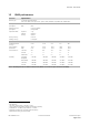
ZOE-M8 - Data Sheet 1.3 GNSS performance Parameter Specification Receiver type 72-channel u-blox M8 engine GPS L1C/A, SBAS L1C/A, QZSS L1C/A, QZSS L1 SAIF, GLONASS L1OF, BeiDou B1I, Galileo E1B/C Accuracy of time pulse signal RMS 99% 30 ns 60 ns Frequency of time pulse signal Operational limits 0.25 Hz to10 MHz (configurable) 1 Dynamics ≤4g Altitude 50,000 m Velocity 500 m/s 2 Velocity accuracy Heading accuracy 0.05 m/s 2 0.
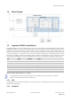
ZOE-M8 - Data Sheet 1.4 Block diagram Figure 1: ZOE-M8 block diagram 1.5 Supported GNSS constellations ZOE-M8 GNSS SiPs are concurrent GNSS receivers which can receive and track multiple GNSS systems: GPS, Galileo, GLONASS and BeiDou. Owing to the dual-frequency RF front-end architecture, either GLONASS or BeiDou can be processed concurrently with GPS and Galileo signals, thereby providing reception of three GNSS systems.
ZOE-M8 - Data Sheet The ZOE-M8 SiPs can receive and process the GLONASS satellite system as an alternative to the US-based Global Positioning System (GPS). The u-blox ZOE-M8 positioning SiPs are designed to receive and track the L1OF signals that GLONASS provides at 1602 MHz + k*562.5 kHz, where k is the satellite’s frequency channel number (k = -7, ..., 5, 6). The ability to receive and track GLONASS L1OF satellite signals allows the design of GLONASS receivers where required by regulations.
ZOE-M8 - Data Sheet 1.6.3 AssistNow™ Autonomous AssistNow Autonomous provides aiding information without the need for a host or external network connection. Based on previous broadcast satellite ephemeris data downloaded to and stored by the GNSS receiver, AssistNow Autonomous automatically generates accurate predictions of satellite orbital data (“AssistNow Autonomous data”) that is usable for future GNSS position fixes.
ZOE-M8 - Data Sheet Message Type Description 1 Differential GPS Corrections 2 Delta Differential GPS Corrections 3 9 GPS Reference Station Parameters GPS Partial Correction Set Table 3: Supported RTCM 2.3 messages RTCM corrections cannot be used together with SBAS. For more details, see the u-blox 8 / u-blox M8 Receiver Description Including Protocol Specification [2]. 1.
ZOE-M8 - Data Sheet The receiver combines a number of checks on the received signals looking for inconsistencies across several parameters. This feature does not guarantee to detect all spoofing attacks. 1.14 EXTINT: External interrupt EXTINT is an external interrupt pin with fixed input voltage thresholds with respect to VCC. It can be used for control of the receiver or for aiding.
ZOE-M8 - Data Sheet The ZOE-M8 SiPs make use of a UART interface, which can be used for communication to a host. It supports configurable baud rates. For supported transfer rates, see the u-blox 8 / u-blox M8 Receiver Description Including Protocol Specification [2]. Designs must allow access to the UART and the SAFEBOOT_N pin for future service, updates and reconfiguration. 1.17.2 SPI The SPI interface is designed to allow communication to a host CPU. The interface can be operated in slave mode only.
ZOE-M8 - Data Sheet 1.19 Safe Boot Mode If Pin C4 (SAFEBOOT_N) is set to logical “0” at startup, the ZOE-M8 receiver enters Safe Boot Mode. In this mode, the receiver does not calculate positioning data, but is in a defined state that allows such actions as programming the flash memory in production, or recovering a corrupted flash memory. For more information about Safe Boot Mode, see the ZOE-M8 Hardware Integration Manual [1]. 1.
ZOE-M8 - Data Sheet u-blox ZOE-M8 SiPs can be configured to run in either continuous mode or a choice of power save mode configurations. A template of power mode settings can be used to easily select typical power mode setups to cover the majority of users’ requirements. For specific power saving applications the user has the option to fully configure via the power save mode configuration. More information see the section 1.22.2.2.
ZOE-M8 - Data Sheet 2 Pin definition 2.1 Pin assignment This section shows the pin assignments. Most PIOs are configurable and have shared functions. Use special care when designing with these pins since the overall function of the device can be affected. The default configuration of the PIOs is listed in Table 7 below. For more information, see the ZOE-M8 Hardware Integration Manual [1].
ZOE-M8 - Data Sheet For multiple function PIOs, select the specific signal by sending the specific configuration message. Pin # SiP Name I/O Description Remark A1 A2 All All GND SDA / SPI CS_N I/O Ground Serial interface. See section 1.17.5. Leave open if not used. A3 A4 All All GND RF_IN I Ground GNSS signal input A5 A6 All All GND Reserved I/O Ground Reserved.
ZOE-M8 - Data Sheet Pin # SiP Name I/O Description Remark ZOE-M8Q V_DCDC_OUT O DCDC converter output Connect to VCC if DCDC not used H9 J1 All All V_BCKP VCC I I Backup supply Supply voltage Clean and stable supply needed J2 J3 All All VCC GND I Supply voltage Ground Clean and stable supply needed J4 J5 All All RXD/SPI MOSI TXD/SPI MISO I O Serial interface. See section 1.17.5. Serial interface. See section 1.17.5. Leave open if not used. Leave open if not used.
ZOE-M8 - Data Sheet 3 Electrical specification The limiting values given are in accordance with the Absolute Maximum Rating System (IEC 134). Stress above one or more of the limiting values may cause permanent damage to the device. These are stress ratings only, and operation of the device at these or at any other conditions above those given in the Characteristics sections of the specification is not implied. Exposure to limiting values for extended periods may affect device reliability.
ZOE-M8 - Data Sheet 3.2 Operating conditions The test conditions specified in Table 9 apply to all characteristics defined in this section. Symbol Parameter SiP Min Typical Max Unit Tamb Ambient temperature All -40 +25 +85 °C GND Ground All 0 V VCC Supply voltage Supply voltage ZOE-M8G ZOE-M8Q 1.8 3.0 V V Core supply voltage Backup battery supply voltage ZOE-M8Q All 3.0 V 1.8 V Receiver Chain Noise Figure All 2.
ZOE-M8 - Data Sheet Symbol Parameter SiP RTC_Fxtal RTC crystal resonant frequency All RTC_T_start RTC startup time All 0.2 RTC_Amp 32768 Hz OSC oscillation amplitude All 50 RTC_ESR 32768 Hz Xtal equivalent series resistance All RTC_CL RTC integrated load capacitance All ESR = 80 kΩ DCDC_eff DC/DC efficiency ZOE-M8Q 4 V_DCDC_out DC/DC output voltage ZOE-M8Q DC/DC enabled Condition Min. Typ. Max. 32768 4 3.3 V @ input, 4 mA – 80 mA, External components: L = 2.2 µH, C = 4.
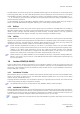
ZOE-M8 - Data Sheet 4.2 SPI timing diagrams In order to avoid incorrect operation of the SPI, the user needs to comply with certain timing conditions. The following signals need to be considered for timing constraints: Symbol Description SPI CS_N (SS_N) Slave select signal SPI CLK (SCK) Slave clock signal Table 14: Symbol description Figure 4: SPI timing diagram 4.2.1 Timing recommendations The recommendations below are based on a firmware running from SQI flash memory.
ZOE-M8 - Data Sheet 5 Mechanical specification Figure 5: Mechanical drawing for ZOE-M8 (S-LGA), bottom view UBX-16008094 - R07 Production Information Mechanical specification Page 22 of 29
ZOE-M8 - Data Sheet 6 Reliability tests and approvals 6.1 Reliability tests ZOE-M8 SiPs are based on AEC-Q100 qualified GNSS chips. Qualification requirements are according to JEDEC standards JESD47 “Stress-Test-Driven Qualification of Integrated Circuits" and ISO 16750 "Road vehicles – environmental conditions and testing for electrical and electronic equipment”. 6.
ZOE-M8 - Data Sheet 7 Product handling 7.1 Packaging ZOE-M8 SiPs are delivered as hermetically sealed, reeled tapes in order to enable efficient production lot set-up and tear-down. For more information about packaging, see the u-blox Package Information Guide [3]. 7.1.1 Reels ZOE-M8 SiPs are deliverable in quantities of 1000 pieces on a reel. The ZOE-M8 SiPs are shipped on Reel Type D, as described in the u-blox Package Information Guide [3]. 7.1.
ZOE-M8 - Data Sheet 7.2 Shipment, storage and handling The absolute maximum rating of the storage temperature specified in the section 3.1 applies to the storage of the SiP both before and after soldering. Required storage conditions for SiPs in reeled tapes and for naked SiPs before soldering, other important information regarding shipment, storage and handling are described in the u-blox Package Information Guide [3]. 7.
ZOE-M8 - Data Sheet 8 Default messages Interface Settings UART Output 9600 Baud, 8 bits, no parity bit, 1 stop bit Configured to transmit both NMEA and UBX protocols, but only the following NMEA (no UBX) messages have been activated at start-up: GGA, GLL, GSA, GSV, RMC, VTG, TXT 9600 Baud, 8 bits, no parity bit, 1 stop bit, Autobauding disabled Automatically accepts following protocols without need of explicit configuration: UBX, NMEA, RTCM The GNSS receiver supports interleaved UBX and NMEA messages.
ZOE-M8 - Data Sheet 9 Labeling and ordering information 9.1 Product labeling The labeling of u-blox M8 GNSS products includes important product information. The location of the ZOE-M8 product type number is shown in Figure 7. 010 ZOEM8G Stands for product type number: ZOE-M8G-0-10 Figure 7: Description of ZOE-M8 product label (top view) 9.2 Explanation of product codes Three different product code formats are used.
ZOE-M8 - Data Sheet Related documents [1] ZOE-M8 Hardware Integration Manual, Document No. UBX-16030136 [2] u-blox 8 / u-blox M8 Receiver Description Including Protocol Specification (public version), Document No. UBX-13003221 [3] u-blox Package Information Guide, Document No. UBX-14001652 [4] [5] RTCM 10402.3 Recommended Standards for Differential GNSS, Ver. 2.3, RTCM AUG. 20, 2001 Radio Resource LCS Protocol (RRLP), (3GPP TS 44.031 version 11.0.
ZOE-M8 - Data Sheet Contact For complete contact information, visit us at www.u-blox.com u-blox Offices North, Central and South America u-blox America, Inc. Phone: E-mail: +1 703 483 3180 info_us@u-blox.com Regional Office West Coast: Phone: +1 408 573 3640 E-mail: info_us@u-blox.com Technical Support: Phone: E-mail: Headquarters Europe, Middle East, Africa Asia, Australia, Pacific u-blox AG Phone: E-mail: Support: Phone: E-mail: Support: +41 44 722 74 44 info@u-blox.com support@u-blox.