
User Manual


ZED-F9P-Data Sheet
UBX-17051259 - R02
4 Electrical specification Page 13 of 24
Advance Information
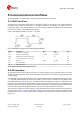
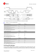
Parameter Symbol Min Typical Max Units Condition
Receiver Chain Noise Figure
8
NFtot 9.5 dB
Operating temperature Topr -40 85 °C
Table 10: Operating conditions
Operation beyond the specified operating conditions can affect device reliability.
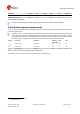
4.3 Indicative power requirements
Table 11 lists examples of the total system supply current including RF and baseband section for
a possible application.
Values in Table 11 are provided for customer information only as an example of typical current
requirements. Values are characterized on samples with a commanded cold start – actual
power requirements can vary depending on FW version used, external circuitry, number of SVs
tracked, signal strength, type and time of start, duration, and conditions of test.
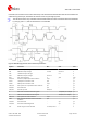
Symbol Parameter Conditions GPS+GLO
+GAL+BDS
GPS Unit
I
PEAK
Peak current Acquisition 130 120 mA
I
VCC
9
VCC current Acquisition 90 75 mA
I
VCC
9
VCC current Tracking 85 68 mA
Table 11: Currents to calculate the indicative power requirements
All values in Table 11 are measured at 25°C ambient temperature.
8
Only valid for the GPS L1 band
9
Simulated signal