
User Manual


ZED-F9P-Data Sheet
UBX-17051259 - R02
4 Electrical specification Page 12 of 24
Advance Information
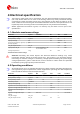
4 Electrical specification
The limiting values given are in accordance with the Absolute Maximum Rating System
(IEC 134). Stress above one or more of the limiting values may cause permanent damage
to the device. These are stress ratings only, and operation of the device at these or at any
other conditions above those given in the Characteristics sections of the specification is not
implied. Exposure to limiting values for extended periods may affect device reliability.
Where application information is given, it is advisory only and does not form part of the
specification.
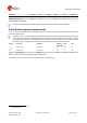
4.1 Absolute maximum ratings
Parameter Symbol Condition Min Max Units
Power supply voltage VCC -0.5 3.6 V
Backup battery voltage V_BCKP -0.5 3.6 V
Input pin voltage Vin -0.5 VCC+0.5 V
DC current through any digital I/O pin
(except supplies)
Ipin TBD mA
VCC_RF output current ICC_RF 100 mA
Input power at RF_IN Prfin source impedance = 50
Ω,
continuous wave
15 dBm
Storage temperature Tstg -40 +85 °C
Table 9: Absolute maximum ratings
Attention Stressing the device beyond the Absolute Maximum Ratings may cause
permanent damage. These are stress ratings only. The product is not protected against
overvoltage or reversed voltages. If necessary, voltage spikes exceeding the power supply
voltage specification, given in table above, must be limited to values within the specified
boundaries by using appropriate protection diodes.
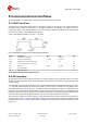
4.2 Operating conditions
All specifications are at an ambient temperature of 25°C. Extreme operating temperatures
can significantly impact specification values. Applications operating near the temperature
limits should be tested to ensure the specification.
Parameter Symbol Min Typical Max Units Condition
Power supply voltage VCC 2.7 3.0 3.6 V
Backup battery voltage V_BCKP 1.65 3.6 V
Backup battery current I_BCKP 80 µA
SW backup current I_SWBCKP 1.4 mA
Input pin voltage range Vin 0 VCC V
Digital IO Pin Low level input voltage Vil 0 0.8 V
Digital IO Pin High level input voltage Vih 2 VCC+0.3 V
Digital IO Pin Low level output
voltage
Vol 0.4 V Iol = 2 mA
Digital IO Pin High level output
voltage
Voh VCC – 0.4 V Ioh = 2 mA
VCC_RF voltage VCC_RF VCC - 0.1 V
VCC_RF output current ICC_RF 50 mA