
Data Sheet

Copyright © 2013 Future Technology Devices International Limited 40
FT231X USB TO FULL HANDSHAKE UART IC
Datasheet
Version 1.2
Document No.: FT_000565 Clearance No.: FTDI# 261
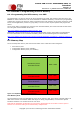
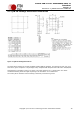
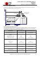
9.5 Solder Reflow Profile
The FT231X is supplied in Pb free 20 LD SSOP and QFN-20 packages. The recommended solder reflow
profile for both package options is shown in Figure 9.5.
Figure 9.5 FT231X Solder Reflow Profile
The recommended values for the solder reflow profile are detailed in Table 9.1. Values are shown for both
a completely Pb free solder process (i.e. the FT231X is used with Pb free solder), and for a non-Pb free
solder process (i.e. the FT231X is used with non-Pb free solder).
Profile Feature
Pb Free Solder Process
Non-Pb Free Solder Process
Average Ramp Up Rate (T
s
to T
p
)
3°C / second Max.
3°C / Second Max.
Preheat
- Temperature Min (T
s
Min.)
- Temperature Max (T
s
Max.)
- Time (t
s
Min to t
s
Max)
150°C
200°C
60 to 120 seconds
100°C
150°C
60 to 120 seconds
Time Maintained Above Critical Temperature
T
L
:
- Temperature (T
L
)
- Time (t
L
)
217°C
60 to 150 seconds
183°C
60 to 150 seconds
Peak Temperature (T
p
)
260°C
240°C
Time within 5°C of actual Peak Temperature
(t
p
)
20 to 40 seconds
20 to 40 seconds
Ramp Down Rate
6°C / second Max.
6°C / second Max.
Time for T= 25°C to Peak Temperature, T
p
8 minutes Max.
6 minutes Max.
Table 9.1 Reflow Profile Parameter Values
Critical Zone: when
T is in the range
T to T
Temperature, T (Degrees C)
Time, t (seconds)
25
P
T = 25º C to T
t
p
T
p
T
L
t
Preheat
S
t
L
Ramp Up
L
p
Ramp
Down
T Max
S
T Min
S