
Data Sheet


Copyright © 2013 Future Technology Devices International Limited 24
FT231X USB TO FULL HANDSHAKE UART IC
Datasheet
Version 1.2
Document No.: FT_000565 Clearance No.: FTDI# 261
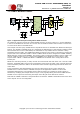
6.3 USB Bus Powered with Power Switching Configuration
FT231X
1
2
3
4
5
SHIELD
Ferrite
Bead
GND
GND
VCC
GND
VCC
3V3OUT
USBDM
USBDP
VCCIO
AGND
GND
RESET#
100nF
100nF
10nF
4.7uF+
CBUS3
PWREN#
10k
1k
Switched 5V Power to
External Logic
0.1uF0.1uF
P Channel Power
MOSFET
27R
27R
GND
47pF47pF
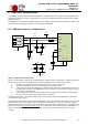
Figure 6.3 Bus Powered with Power Switching Configuration
A requirement of USB bus powered applications, is when in USB suspend mode, the application draws a
total current of less than 2.5mA. This requirement includes external logic. Some external logic has the
ability to power itself down into a low current state by monitoring the PWREN# signal. For external logic
that cannot power itself down in this way, the FT231X provides a simple but effective method of turning
off power during the USB suspend mode.
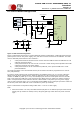
Figure 6.3 shows an example of using a discrete P-Channel MOSFET to control the power to external
logic. A suitable device to do this is an International Rectifier (www.irf.com) IRLML6402, or equivalent. It
is recommended that a “soft start” circuit consisting of a 1kΩ series resistor and a 0.1μF capacitor is used
to limit the current surge when the MOSFET turns on. Without the soft start circuit it is possible that the
transient power surge, caused when the MOSFET switches on, will reset the FT231X or the USB host/hub
controller. The soft start circuit example shown in Figure 6.3 powers up with a slew rate of
approximaely12.5V/ms. Thus supply voltage to external logic transitions from GND to +5V in
approximately 400 microseconds.
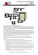
As an alternative to the MOSFET, a dedicated power switch IC with inbuilt “soft-start” can be used. A
suitable power switch IC for such an application is the Micrel (www.micrel.com) MIC2025-2BM or
equivalent.
With power switching controlled designs the following should be noted:
i) The external logic to which the power is being switched should have its own reset circuitry to
automatically reset the logic when power is re-applied when moving out of suspend mode.
ii) Set the Pull-down on Suspend option in the internal FT231X MTP memory.
iii) One of the CBUS Pins should be configured as PWREN# in the internal FT231X MTP memory, and
used to switch the power supply to the external circuitry. This should be pulled high through a 10
kΩ resistor.
iv) For USB high-power bus powered applications (one that consumes greater than 100mA, and up
to 500mA of current from the USB bus), the power consumption of the application must be set in
the Max Power field in the internal FT231X MTP memory. A high-power bus powered application
uses the descriptor in the internal FT231X MTP memory to inform the system of its power
requirements.
v) PWREN# gets its VCC from VCCIO. For designs using 3V3 logic, ensure VCCIO is not powered
down using the external logic. In this case use the +3V3OUT.