
Data Sheet
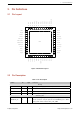
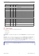

2.3 Power Scheme 2 PIN DEFINITIONS
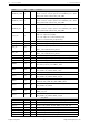
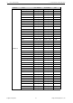
Name No. Type Function
SD_DATA_0 32 I/O GPIO7, SD_DATA0, SPIQ, HS1_DATA0, U2RTS
SD_DATA_1 33 I/O GPIO8, SD_DATA1, SPID, HS1_DATA1, U2CTS
VDD3P3_CPU
GPIO5 34 I/O GPIO5, VSPICS0, HS1_DATA6, EMAC_RX_CLK
GPIO18 35 I/O GPIO18, VSPICLK, HS1_DATA7
GPIO23 36 I/O GPIO23, VSPID, HS1_STROBE
VDD3P3_CPU 37 P CPU IO power supply input (1.8V - 3.3V)
GPIO19 38 I/O GPIO19, VSPIQ, U0CTS, EMAC_TXD0
GPIO22 39 I/O GPIO22, VSPIWP, U0RTS, EMAC_TXD1
U0RXD 40 I/O GPIO3, U0RXD, CLK_OUT2
U0TXD 41 I/O GPIO1, U0TXD, CLK_OUT3, EMAC_RXD2
GPIO21 42 I/O GPIO21, VSPIHD, EMAC_TX_EN
Analog
VDDA 43 I/O Analog power supply (2.3V - 3.6V)
XTAL_N 44 O External crystal output
XTAL_P 45 I External crystal input
VDDA 46 P Digital power supply for PLL (2.3V - 3.6V)
CAP2 47 I
Connects with a 3 nF capacitor and 20 kΩ resistor in parallel to
CAP1
CAP1 48 I Connects with a 10 nF series capacitor to ground
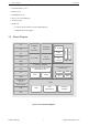
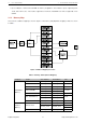
2.3 Power Scheme
ESP32 digital pins are divided into three different power domains:
• VDD3P3_RTC
• VDD3P3_CPU
• VDD_SDIO
VDD3P3_RTC is also the input power supply for RTC and CPU. VDD3P3_CPU is also the input power supply for
CPU.
VDD_SDIO connects to the output of an internal LDO, whose input is VDD3P3_RTC. When VDD_SDIO is con-
nected to the same PCB net together with VDD3P3_RTC; the internal LDO is disabled automatically.
The internal LDO can be configured as 1.8V, or the same voltage as VDD3P3_RTC. It can be powered off via
software to minimize the current of Flash/SRAM during the Deep-sleep mode.
Note:
It is required that the power supply of VDD3P3_RTC, VDD3P3_CPU and analog must be stable before the pin CHIP_PU
is set at high level.
Espressif Systems 8 http://www.espressif.com