
Data Sheet

DS18B20
25 of 27
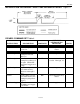
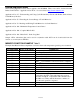
AC ELECTRICAL CHARACTERISTICS: (-55°C to +125°C; V
DD
=3.0V to 5.5V)
PARAMETER SYMBOL CONDITION MIN TYP MAX UNITS NOTES
Temperature
Conversion
t
CONV
9 bit 93.75 ms
Time 10 bit 187.5
11 bit 375
12 bit 750
Time Slot t
SLOT
60 120 µs
Recovery Time t
REC
1µs
Write 0 Low Time r
LOW0
60 120 µs
Write 1 Low Time t
LOW1
115µs
Read Data Valid t
RDV
15 µs
Reset Time High t
RSTH
480 µs
Reset Time Low t
RSTL
480 µs 9
Presence Detect High t
PDHIGH
15 60 µs
Presence Detect Low t
PDLOW
60 240 µs
Capacitance C
IN/OUT
25 pF
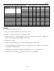
NOTES:
1. All voltages are referenced to ground.
2. Logic one voltages are specified at a source current of 1 mA.
3. Logic zero voltages are specified at a sink current of 4 mA.
4. Active current refers to either temperature conversion or writing to the E
2
memory. Writing to E
2
memory consumes approximately 200 µA for up to 10 ms.
5. Input load is to ground.
6. Standby current specified up to 70°C. Standby current typically is 3 µA at 125°C.
7. To always guarantee a presence pulse under low voltage parasite power conditions, V
ILMAX
may have
to be reduced to as much as 0.5V.
8. To minimize I
DDS
, DQ should be: GND ≤ DQ ≤ GND +0.3V or V
DD
– 0.3V ≤ DQ ≤ V
DD
.
9. Under parasite power, the max t
RSTL
before a power on reset occurs is 960 µS.