
Data Sheet

DS18B20
13 of 27
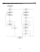
8. The bus master writes a 0-bit. This deselects ROM1, leaving ROM4 as the only device still
connected.
9. The bus master reads the remainder of the ROM bits for ROM4 and continues to access the part if
desired. This completes the first pass and uniquely identifies one part on the 1-Wire bus.
10. The bus master starts a new ROM search sequence by repeating steps 1 through 7.
11. The bus master writes a 1-bit. This decouples ROM4, leaving only ROM1 still coupled.
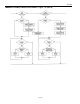
12. The bus master reads the remainder of the ROM bits for ROM1 and communicates to the underlying
logic if desired. This completes the second ROM search pass, in which another of the ROMs was
found.
13. The bus master starts a new ROM search by repeating steps 1 through 3.
14. The bus master writes a 1-bit. This deselects ROM1 and ROM4 for the remainder of this search pass,
leaving only ROM2 and ROM3 coupled to the system.
15. The bus master executes two Read time slots and receives two 0s.
16. The bus master writes a 0-bit. This decouples ROM3 leaving only ROM2.
17. The bus master reads the remainder of the ROM bits for ROM2 and communicates to the underlying
logic if desired. This completes the third ROM search pass, in which another of the ROMs was
found.
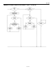
18. The bus master starts a new ROM search by repeating steps 13 through 15.
19. The bus master writes a 1-bit. This decouples ROM2, leaving only ROM3.
20. The bus master reads the remainder of the ROM bits for ROM3 and communicates to the underlying
logic if desired. This completes the fourth ROM search pass, in which another of the ROMs was
found.
NOTE:
The bus master learns the unique ID number (ROM data pattern) of one 1-Wire device on each ROM
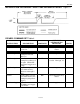
Search operation. The time required to derive the part’s unique ROM code is:
960 µs + (8 + 3 x 64) 61 µs = 13.16 ms
The bus master is therefore capable of identifying 75 different 1-Wire devices per second.
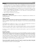
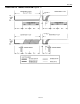
I/O SIGNALING
The DS18B20 requires strict protocols to insure data integrity. The protocol consists of several types of
signaling on one line: reset pulse, presence pulse, write 0, write 1, read 0, and read 1. All of these signals,
with the exception of the presence pulse, are initiated by the bus master.