
Datasheet


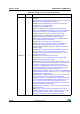
Table Of Contents
- Table 1. Device summary
- 1 Introduction
- 2 Description
- Table 2. STM32F405xx and STM32F407xx: features and peripheral counts (continued)
- 2.1 Full compatibility throughout the family
- 2.2 Device overview
- 2.2.1 ARM® Cortex®-M4 core with FPU and embedded Flash and SRAM
- 2.2.2 Adaptive real-time memory accelerator (ART Accelerator™)
- 2.2.3 Memory protection unit
- 2.2.4 Embedded Flash memory
- 2.2.5 CRC (cyclic redundancy check) calculation unit
- 2.2.6 Embedded SRAM
- 2.2.7 Multi-AHB bus matrix
- 2.2.8 DMA controller (DMA)
- 2.2.9 Flexible static memory controller (FSMC)
- 2.2.10 Nested vectored interrupt controller (NVIC)
- 2.2.11 External interrupt/event controller (EXTI)
- 2.2.12 Clocks and startup
- 2.2.13 Boot modes
- 2.2.14 Power supply schemes
- 2.2.15 Power supply supervisor
- 2.2.16 Voltage regulator
- 2.2.17 Regulator ON/OFF and internal reset ON/OFF availability
- 2.2.18 Real-time clock (RTC), backup SRAM and backup registers
- 2.2.19 Low-power modes
- 2.2.20 VBAT operation
- 2.2.21 Timers and watchdogs
- 2.2.22 Inter-integrated circuit interface (I²C)
- 2.2.23 Universal synchronous/asynchronous receiver transmitters (USART)
- 2.2.24 Serial peripheral interface (SPI)
- 2.2.25 Inter-integrated sound (I2S)
- 2.2.26 Audio PLL (PLLI2S)
- 2.2.27 Secure digital input/output interface (SDIO)
- 2.2.28 Ethernet MAC interface with dedicated DMA and IEEE 1588 support
- 2.2.29 Controller area network (bxCAN)
- 2.2.30 Universal serial bus on-the-go full-speed (OTG_FS)
- 2.2.31 Universal serial bus on-the-go high-speed (OTG_HS)
- 2.2.32 Digital camera interface (DCMI)
- 2.2.33 Random number generator (RNG)
- 2.2.34 General-purpose input/outputs (GPIOs)
- 2.2.35 Analog-to-digital converters (ADCs)
- 2.2.36 Temperature sensor
- 2.2.37 Digital-to-analog converter (DAC)
- 2.2.38 Serial wire JTAG debug port (SWJ-DP)
- 2.2.39 Embedded Trace Macrocell™
- 3 Pinouts and pin description
- 4 Memory mapping
- 5 Electrical characteristics
- 5.1 Parameter conditions
- 5.2 Absolute maximum ratings
- 5.3 Operating conditions
- 5.3.1 General operating conditions
- 5.3.2 VCAP_1/VCAP_2 external capacitor
- 5.3.3 Operating conditions at power-up / power-down (regulator ON)
- 5.3.4 Operating conditions at power-up / power-down (regulator OFF)
- 5.3.5 Embedded reset and power control block characteristics
- 5.3.6 Supply current characteristics
- Table 20. Typical and maximum current consumption in Run mode, code with data processing running from Flash memory (ART accelerator enabled) or RAM
- Table 21. Typical and maximum current consumption in Run mode, code with data processing running from Flash memory (ART accelerator disabled)
- Table 22. Typical and maximum current consumption in Sleep mode
- Table 23. Typical and maximum current consumptions in Stop mode
- Table 24. Typical and maximum current consumptions in Standby mode
- Table 25. Typical and maximum current consumptions in VBAT mode
- Table 26. Typical current consumption in Run mode, code with data processing running from Flash memory, regulator ON (ART accelerator enabled except prefetch), VDD = 1.8 V
- Table 27. Switching output I/O current consumption
- Table 28. Peripheral current consumption
- 5.3.7 Wakeup time from low-power mode
- 5.3.8 External clock source characteristics
- 5.3.9 Internal clock source characteristics
- 5.3.10 PLL characteristics
- 5.3.11 PLL spread spectrum clock generation (SSCG) characteristics
- 5.3.12 Memory characteristics
- 5.3.13 EMC characteristics
- 5.3.14 Absolute maximum ratings (electrical sensitivity)
- 5.3.15 I/O current injection characteristics
- 5.3.16 I/O port characteristics
- 5.3.17 NRST pin characteristics
- 5.3.18 TIM timer characteristics
- 5.3.19 Communications interfaces
- Table 54. I2C analog filter characteristics
- Table 55. SPI dynamic characteristics
- Table 56. I2S dynamic characteristics
- Table 57. USB OTG FS startup time
- Table 58. USB OTG FS DC electrical characteristics
- Table 59. USB OTG FS electrical characteristics
- Table 60. USB HS DC electrical characteristics
- Table 61. USB HS clock timing parameters
- Table 62. ULPI timing
- Table 63. Ethernet DC electrical characteristics
- Table 64. Dynamic characteristics: Eternity MAC signals for SMI
- Table 65. Dynamic characteristics: Ethernet MAC signals for RMII
- Table 66. Dynamic characteristics: Ethernet MAC signals for MII
- 5.3.20 CAN (controller area network) interface
- 5.3.21 12-bit ADC characteristics
- 5.3.22 Temperature sensor characteristics
- 5.3.23 VBAT monitoring characteristics
- 5.3.24 Embedded reference voltage
- 5.3.25 DAC electrical characteristics
- 5.3.26 FSMC characteristics
- Table 75. Asynchronous non-multiplexed SRAM/PSRAM/NOR read timings
- Table 76. Asynchronous non-multiplexed SRAM/PSRAM/NOR write timings
- Table 77. Asynchronous multiplexed PSRAM/NOR read timings
- Table 78. Asynchronous multiplexed PSRAM/NOR write timings
- Table 79. Synchronous multiplexed NOR/PSRAM read timings
- Table 80. Synchronous multiplexed PSRAM write timings
- Table 81. Synchronous non-multiplexed NOR/PSRAM read timings
- Table 82. Synchronous non-multiplexed PSRAM write timings
- Table 83. Switching characteristics for PC Card/CF read and write cycles in attribute/common space
- Table 84. Switching characteristics for PC Card/CF read and write cycles in I/O space
- Table 85. Switching characteristics for NAND Flash read cycles
- Table 86. Switching characteristics for NAND Flash write cycles
- 5.3.27 Camera interface (DCMI) timing specifications
- 5.3.28 SD/SDIO MMC card host interface (SDIO) characteristics
- 5.3.29 RTC characteristics
- 6 Package information
- 7 Part numbering
- Appendix A Application block diagrams
- 8 Revision history

Revision history STM32F405xx, STM32F407xx
194/202 DocID022152 Rev 8
31-May-2012 3
Updated Figure 5: STM32F40xxx block diagram and Figure 7: Power
supply supervisor interconnection with internal reset OFF
Added SDIO, added notes related to FSMC and SPI/I2S in Table 2:
STM32F405xx and STM32F407xx: features and peripheral counts.
Starting from Silicon revision Z, USB OTG full-speed interface is now
available for all STM32F405xx devices.
Added full information on WLCSP90 package together with
corresponding part numbers.
Changed number of AHB buses to 3.
Modified available Flash memory sizes in Section 2.2.4: Embedded
Flash memory.
Modified number of maskable interrupt channels in Section 2.2.10:
Nested vectored interrupt controller (NVIC).
Updated case of Regulator ON/internal reset ON, Regulator
ON/internal reset OFF, and Regulator OFF/internal reset ON in
Section 2.2.16: Voltage regulator.
Updated standby mode description in Section 2.2.19: Low-power
modes.
Added Note 1 below Figure 16: STM32F40xxx UFBGA176 ballout.
Added Note 1 below Figure 17: STM32F40xxx WLCSP90 ballout.
Updated Table 7: STM32F40xxx pin and ball definitions.
Added Table 8: FSMC pin definition.
Removed OTG_HS_INTN alternate function in Table 7: STM32F40xxx
pin and ball definitions and Table 9: Alternate function mapping.
Removed I2S2_WS on PB6/AF5 in Table 9: Alternate function
mapping.
Replaced JTRST by NJTRST, removed
ETH_RMII _TX_CLK, and
modified I2S3ext_SD on PC11 in Table 9: Alternate function mapping.
Added Table 10: register boundary addresses.
Updated Figure 18: STM32F40xxx memory map.
Updated V
DDA
and V
REF+
decoupling capacitor in Figure 21: Power
supply scheme.
Added power dissipation maximum value for WLCSP90 in Table 14:
General operating conditions.
Updated V
POR/PDR
in Table 19: Embedded reset and power control
block characteristics.
Updated notes in Table 21: Typical and maximum current consumption
in Run mode, code with data processing running from Flash memory
(ART accelerator disabled), Table 20: Typical and maximum current
consumption in Run mode, code with data processing running from
Flash memory (ART accelerator enabled) or RAM, and Table 22:
Typical and maximum current consumption in Sleep mode.
Updated maximum current consumption at T
A
= 25 °n Table 23:
Typical and maximum current consumptions in Stop mode.
Table 100. Document revision history (continued)
Date Revision Changes