
User Manual


Apollo3 Blue Datasheet
DS-A3-0p9p1 Page 793 of 909 2019 Ambiq Micro, Inc.
All rights reserved.
21.15PDM Interface
21.16I2S Interface
21.17Universal Asynchronous Receiver/Transmitter (UART)
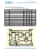
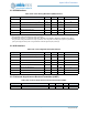
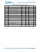
Table 1158: Pulse Density Modulation (PDM) Interface
Symbol Parameter Min Typ Max Unit
DC
PDMCLK
PDM clock duty cycle
a
a. Applicable when F
PDMCLK
<= 2.4 MHz and PDM_PCFG_MCLKDIV set to MCKDIV1, MCKDIV2 or MCKDIV4 only. PDM_P-
CFG_MCLKDIV setting of MCKDIV3 has a duty cycle of 67%.
45
-55 %
DC
PDMCLK_HI
PDM high frequency clock duty cycle
b
b. Applicable when F
PDMCLK
> 2.4 MHz and PDM_PCFG_MCLKDIV set to MCKDIV1, MCKDIV2 or MCKDIV4 only. PDM_P-
CFG_MCLKDIV setting of MCKDIV3 has a duty cycle of 67%. Also, using Pad 37 for PDM_CLK supports only the lower fre-
quency DC range (DC
PDMCLK
) and is not guaranteed to meet the higher frequency DC range.
48
-52 %
T
PDM_RISE
PDM clock and data rise time - - TBD ns
T
PDM_FALL
PDM clock and data fall time - - TBD ns
T
SU_PDM
PDM input data setup time - -TBD ns
T
HD_PDM
PDM input data hold time TBD - - ns
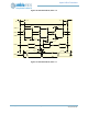
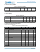
Table 1159: Inter-Integrated Serial (I2S) Interface
Symbol Parameter Min Typ Max Unit
F
BCLK
I2S input BCLK frequency range TBD TBD MHz
F
WDCLK
I2S input WDCLK frequency range TBD TBD MHz
DC
BCLK
I2S BCLK duty cycle 40 - 60 %
DC
WDCLK
I2S WDCLK duty cycle 40 - 69 %
T
I2S_RISE
I2S clock and data rise time - - TBD ns
T
I2S_FALL
I2S clock and data fall time - - TBD ns
T
SU_I2S
I2S input data setup time - - TBD ns
T
HD_I2S
I2S input data hold time TBD - - ns
Table 1160: Universal Asynchronous Receiver/Transmitter (UART)
Symbol Parameter Min Typ Max Unit
F
BAUD
UART baud rate - 921600 bps