
User Manual


Apollo3 Blue Datasheet
DS-A3-0p9p1 Page 788 of 909 2019 Ambiq Micro, Inc.
All rights reserved.
21.12 Inter-Integrated Circuit (I
2
C) Interface
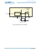
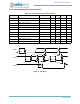
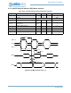
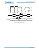
Figure 97. I
2
C Timing
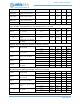
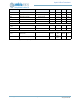
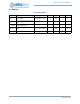
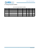
Table 1155: Inter-Integrated Circuit (I
2
C) Interface
Symbol Parameter VCC Min Typ Max Unit
f
SCL
SCL input clock frequency 1.7 V - 3.6 V 10 1000 kHz
t
LOW
Low period of SCL clock 1.7 V - 3.6 V 1.3 µs
t
HIGH
High period of SCL clock 1.7 V - 3.6 V 600 ns
t
RISE
Rise time of SDA and SCL 1.7 V - 3.6 V 300 ns
t
FALL
Fall time of SDA and SCL 1.7 V - 3.6 V 300 ns
t
HD:STA
START condition hold time 1.7 V - 3.6 V 600 ns
t
SU:STA
START condition setup time 1.7 V - 3.6 V 600 ns
t
SU:DAT
SDA setup time 1.7 V - 3.6 V 100 ns
t
HD:DAT
SDA hold time 1.7 V - 3.6 V 0 ns
t
SU:STO
STOP condition setup time 1.7 V - 3.6 V 600 ns
t
BUF
Bus free time before a new transmission 1.7 V - 3.6 V 1.3 µs
t
BUF
SCL
SDA
t
HD:STA
t
LO W
t
RISE
SDA
t
SU:STA
t
HD:DAT
t
HIGH
t
SU:DAT
t
SU:STO
t
FALL