
User Manual


Apollo3 Blue Datasheet
DS-A3-0p9p1 Page 779 of 909 2019 Ambiq Micro, Inc.
All rights reserved.
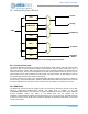
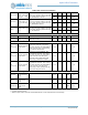
21.6 Bluetooth Low Energy (BLE)
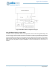
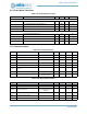
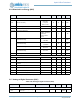
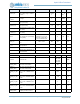
21.7 Analog-to-Digital Converter (ADC)
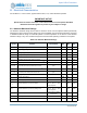
Table 1149: Analog to Digital Converter (ADC)
Symbol
Parameter
a
a. FCC and BQB test reports are available upon request.
Test Conditions Min Typ Max Unit
AC Characteristics - Rx
R
SENS
Receiver sensitivity
1 Mbps BLE ideal
transmitter,
<=37 bytes,
PER < 30.8%
-92 -93 -94 dBm
R
SENS, VAR
Rx sensitivity variance between channels
-0.5 0.5 dB
P
RX,
MAX
Maximum receiver input power
PER < 30.8% 0 dBm
C/I
co-chan-
nel
Co-channel interference
Wanted signal at –
67dBm, modulated
interferer in
channel, PER <
30.8%
7dB
PB
Out of band blocking
30 MHz to
2000 MHz
-5 dBm
Out of band blocking
2003 MHz to
2399 MHz
-15 dBm
Out of band blocking
2484 MHz to
2997 MHz
-15 dBm
Out of band blocking
3000 MHz to
12.75 GHz
-5 dBm
F
ET
Frequency error tolerance -125 125 kHz
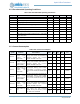
AC Characteristics - Tx
P
OUT_PEAK
Peak output power 3 3.5 4 dBm
P
OUT_AVG
Average Tx output power 2.5 3 3.5 dBm
P
OUT, VAR
Average Tx output power variance between
channels
-0.5 0.5 dB
P
OUT_STEP
Power control step TBD dBm
P
OUT_HD2
Second harmonic output power level -40 -30 dBm
P
OUT_HD3
Third harmonic output power level -40 -30 dBm
P
OUT_HD4
Fourth harmonic output power level -40 -30 dBm
Symbol Parameter Test Conditions Min Typ Max Unit
ANALOG INPUT
V
ADCIN
Input voltage range single-
ended input
0
V
ADCREF
V