
User Manual


Apollo3 Blue Datasheet
DS-A3-0p9p1 Page 772 of 909 2019 Ambiq Micro, Inc.
All rights reserved.
For cost/area constrained designs, the SIMO buck can be disabled and on-die LDO regulators can be
used. In this configuration, the OTP CUSTOMER_TRIM setting must have the SIMO_BUCK_enable set to
‘0’. In this configuration, the SIMO buck will remained powered down.
The SIMO buck cannot be dynamically enabled/disabled after initial device reset.
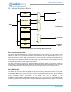
There is also a zero length detect circuit to ensure the regulated voltages from the SIMO buck do not drop
out.
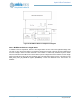
20.3 BLE/Burst Buck
The BLE/Burst buck sources the supplies to the BLE radio subsystem as well as the higher voltage
required to support the burst mode operation. The BLE/Burst buck must be enabled prior to enabling either
the BLE or the burst mode features. The BLE/Burst buck enable bit (See Section Section 3.5.3.1.2.1 on
page 79) can be set at any point after reset in software but should be set prior to enabling either the BLE or
burst mode features. The status of the BLE/Burst buck can be queried via the
PWRCTRL_SUPPLYSTATUS register (See Section Section 3.5.3.1.2.2 on page 79).
For systems that require fast ramp times for the BLE subsystem, the BLE/Burst buck can be enabled by
default at reset by setting the BLE_BUCK_enable and BLE_FEATURE_enable bits in the OTP
CUSTOMER_TRIM field. If set, hardware will control powering up the buck and sequencing the regulation
circuitry as needed at initial power on.
The BLE and burst mode features can be enabled via the FEATUREENABLE register (See Section
Section 3.8.2.7 on page 128). Once enabled, hardware controls all sequencing required to enter/exit the
various power modes of the BLE/Burst regulators regardless of the configuration.
For cost/area constrained designs, the BLE/Burst buck can be disabled and on-die LDO regulators can be
used. In this configuration, the OTP CUSTOMER_TRIM setting must have the BLE_BUCK_enable set to
‘0’. In this configuration, the SIMO buck will remained powered down.
20.3.1 BLE/Burst Buck Ton Adjustment
Calibration logic within the clock generator block works to check the frequency of the Ton clocks going to
the Buck. If the frequency of the Ton clocks is lower than the configured threshold, then the adjustment
logic will reduce the Buck charging time for each cycle, which has the effect of increasing the frequency of
the charging cycles. If the Ton clocks are higher than the configured threshold, then the adjustment logic
will increase the Buck charging time, which has the effect of reducing the frequency of the charging cycle.
The following steps are required to enable the BLE Ton Adjustment:
1. Set the TONADJUSTEN bit field in REG_CLK_GEN_BLEBUCKTONADJ to 0. This will disable
the Adjustment until the programming is done.
2. Set the TONADJUSTPERIOD bits field to the adjustment period required. The longer the adjust-
ment period, the more accurate is the adjustment. The shorter the adjustment period, the faster
will be the adjustment.
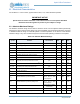
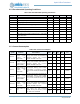
3. Based on the TONADJUSTPERIOD, set the TONHIGHTHRESHOLD and TONLOWTHRESH-
OLD. The suggested values for the high threshold are #15(94KHz) #2A(47Khz) #A6(12Khz)
#29A(3Khz). The suggested values for the low threshold are #A(94KHz) #15(47KHz) #53(12Khz)
#14D(3Khz).
Set the TONADJUSTEN bit field in REG_CLK_GEN_BLEBUCKTONADJ to 1. This will enable the
Adjustment to start.