
User Manual

Apollo3 Blue Datasheet
DS-A3-0p9p1 Page 735 of 909 2019 Ambiq Micro, Inc.
All rights reserved.
configuring the ADC slots and the ADC configuration register between conversion data collections,
followed by disabling the ADC in the power control ADC enable register. Although this mode provides
extremely low power operation, using the ADC in this mode will result in a cold start latency including
reference buffer stabilization delay and a calibration sequence 100’s of microseconds, nominally. In this
mode, the ADC must be reconfigured prior to any subsequent ADC operation.
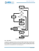
18.4 Interrupts
The ADC has 6 interrupt status bits with corresponding interrupt enable bits, as follows:
1. Conversion Complete Interrupt
2. Scan Complete Interrupt
3. FIFO Overflow Level 1
4. FIFO Overflow Level 2
5. Window Comparator Excursion Interrupt (a.k.a. outside interrupt)
6. Window Comparator Incursion Interrupt (a.k.a. inside interrupt)
7. DMA transfer complete
8. DMA error condition
The window comparator interrupts are discussed above, see Section 18.2.8
There are two interrupts based on the fullness of the FIFO. When the respective interrupts are enabled,
Overflow 1 fires when the FIFO reaches 75% full, viz. 6 entries. Overflow 2 fires when the FIFO is
completely full.
When enabled, the conversion complete interrupt fires when a single slot completes its conversion and the
resulting conversion data is pushed into the FIFO.
When enabled, the scan complete interrupt indicates that all enabled slots have sampled their respective
channels following a trigger event.
When a single slot is enabled and programmed to average over exactly one measurement and the scan
complete and conversion complete interrupts are enabled, a trigger event will result in the conversion
complete and scan complete interrupts firing simultaneously upon completion of the ADC scan. Again, if
both respective interrupts are enabled and a single slot is enabled and programmed to average over 128
measurements, 128 trigger events result in 128 scan complete interrupts and exactly one conversion
complete interrupt following the 128 ADC scans. When multiple slots are enabled with different settings for
the number of measurements to average, the conversion complete interrupt signifies that one or more of
the conversions have completed and the FIFO contains valid data for one or more of the slot conversions.
The DMA transfer complete interrupt is triggered upon completion of the currently configured DMA.
The DMA error interrupt is triggered if the DMA has been instructed to perform an illegal operation such as:
▪ writing outside SRAM
▪ writing to powered-down SRAM (doesn't always work - CORVETTE-628, CORVETTE-800)
▪ popping from the FIFO while the DMA is underway
The DMA supports none of these features.
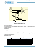
18.5 Voltage Divider and Switchable Battery Load
The Apollo3 Blue MCU’s ADC includes a switchable voltage divider that enables the ADC to measure the
input voltage to the VDD rail. In most systems this will be the battery voltage applied to the MCU chip. The
voltage divider is only switched on when one of the active slots is selecting analog mux channel 15. That is
only when the mode controller is ultimately triggered and powers up the ADC block for a conversion scan
of all active slots. Otherwise, the voltage divider is turned off.