
User Manual

Apollo3 Blue Datasheet
DS-A3-0p9p1 Page 734 of 909 2019 Ambiq Micro, Inc.
All rights reserved.
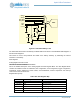
18.3.2 Repeat Mode
Counter/Timer 3A has a bit in its configuration register that allows it to be a source of repetitive triggers for
the ADC. If counter/timer 3 is initialized for this purpose then one only needs to turn on the RPTEN bit in
the ADC configuration registers to enable this mode in the ADC.
NOTE: the mode controller does not process these repetitive triggers from the counter/timer until a first
triggering event occurs from the normal trigger sources. Thus one can select software triggering in the
TRIGSEL field and set up all of the other ADC registers for the desired sample acquisitions. Then one can
write to the software trigger register and the mode controller will enter REPEAT mode. In repeat mode, the
mode controller waits only for each successive counter/timer 3A input to launch a scan of all enabled slots.
18.3.3 Low Power Modes
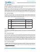
An application may use the ADC in one of three power modes. Each mode has different implications from
overall energy perspective relative to the startup latency from trigger-to-data as well as the standby power
consumed. The table below is intended to provide guidance on which mode may be more effective based
on latency tolerance. This table should only be used as a reference.
18.3.3.1 Low Power Mode 0
Low Power Mode 0 (LPMODE0) enables the lowest latency from trigger to conversion data available. This
mode leaves the reference buffer powered on between scans to bypass any startup latency between
triggers
1
.
18.3.3.2 Low Power Mode 1
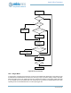
Low power mode 1 (LPMODE1) is a power mode whereby the ADC Digital Controller will automatically
power off the ADC clocks, analog ADC and reference buffer between scans while maintaining ADC
calibration data. This mode may operate autonomously without CPU interaction, even while the CPU is in
sleep or deepsleep mode for repeat mode triggers or hardware triggers. While operating in this mode, the
ADC Digital Controller may be used to burst through multiple scans enabling max sample rate data
collection if the triggers are running at a rate at least 2x the maximum sample rate until the final scan has
completed. When a scan completes without a pending trigger latched, the ADC subsystem will enter a low
power state until the next trigger event.
18.3.3.3 Low Power Mode 2
If desirable, for applications requiring infrequent conversions, software may choose to operate the ADC in
LPMODE2, whereby the full ADC Analog and Digital subsystem remains completely powered off between
samples. In this use case, the software configures the power control ADC enable register followed by
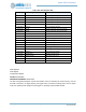
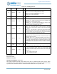
Table 1074: ADC Power Modes
LPMODE Definition Entry Latency
0
ADC is kept active continuously (used in continuous sampling
scenarios)
0
(requires initial
calibration)
1
ADC is mostly powered off between samples, HFRC is duty
cycled between samples. No calibration required after initial
calibration)
<70μs
(shorter for lower
resolution)
2
ADC is completely powered off between samples, HFRC is
duty cycled between samples. Requires recalibration for each
conversion.
<660μs
1.