
User Manual


Apollo3 Blue Datasheet
DS-A3-0p9p1 Page 730 of 909 2019 Ambiq Micro, Inc.
All rights reserved.
hardware populating the 8th valid FIFO entry, the FIFOOVR2 interrupt status bit will be set. In a FIFO
full condition with 16 valid entries, the ADC will not overwrite existing valid FIFO contents. Before sub-
sequent conversions will populate the FIFO with conversion data, software must free an open FIFO
entry by writing to the FIFO Register or by resetting the ADC by disabling and enabling the ADC using
the ADC_CFG register.
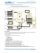
18.2.8 DMA
When enabled, the ADC can use DMA to keep its FIFO serviced and transfers samples to SRAM.
Generally, DMA should be used when the desired use case is autonomous recording of samples to a pre-
allocated buffer in SRAM. The buffer may be byte-aligned but must be a word-multiple in size.
The general steps to enabling ADC DMA are as follows:
1. Ensure SRAM target(s) are powered up.
2. Power up the ADC if it's not already on.
3. Configure ADC slots and ADCCFG register.
4. Set DMATOTCOUNT to the total amount of data to transfer. While the DMA is in progress, this reg-
ister contains a live count of the remaining data to transfer.
5. Configure DMATARGADDR, the SRAM target byte address, for the location in memory of the first
sample to be written by DMA.
6. Select a DMA trigger level by configuring DMATRIGEN to either FIFO 100% full or FIFO 75% full.
This defines what conditions will initiate a DMA transfer.
7. Configure DMACFG, including setting DMAEN.
8. Trigger the ADC multiple times, using either the timer trigger (when using repeat mode), multiple
SW triggers, or multiple external triggers.
Each time the FIFO fills to the appropriate level, the DMA will start and the FIFO will be drained. During this
time, depending on the particular use case, it may be appropriate to put the MCU to sleep or deepsleep.
To monitor progress of the DMA, there is a DMASTAT status register. When the DMA is actively
transferring data from the ADC FIFO to SRAM, DMATIP will be asserted. At the end of an entire transfer
(DMATOTCOUNT reaches 0), then DMACPL will be set. Last, but not least, if an error occurs due to the
DMA being asked to perform an illegal operation, DMAERR will be asserted. Causes of a DMA error
include:
▪ DMA transfers to address outside SRAM memory region
▪ Popping from the FIFO while the DMA is underway
Care must be taken to avoid powering down SRAM that the DMA wants to write to.
If the DMA complete interrupt is enabled, this can be used to wake the MCU from sleep or deepsleep and
communicate that the SRAM buffer has been filled and is ready for processing. The DMA error interrupt
may also be used to signal the MCU that there is a problem with the DMA configuration.
To recover from a DMA error, disable any repeating trigger, disable the DMA via DMACFG's DMAEN field,
and manually drain the ADC FIFO.
Then follow the procedure described above for enabling ADC DMA
while correcting the configuration issue.
Some additional capabilities of the DMA include:
▪ ADC auto-power-off upon DMA completion: This feature, enabled via the DMACFG register's
DPWROFF field, allows the ADC to power off once DMATOTCOUNT reaches zero. Note that this fea-
ture is incompatible with waking the MCU from sleep or deepsleep using the DMA complete interrupt.
▪ Masking FIFOCNT and SLOTNUM data from FIFO data: The DMA engine can be configured to write
only samples to SRAM without the FIFOCNT and SLOTNUM data. This allows the MCU to skip the man-
ual process of masking the potentially undesirable upper bits of each data value written to SRAM.