
User Manual


Apollo3 Blue Datasheet
DS-A3-0p9p1 Page 729 of 909 2019 Ambiq Micro, Inc.
All rights reserved.
Software accesses the contents of the FIFO through the ADCFIFO register. This register will be written by
the ADC digital controller simultaneous with the conversion complete interrupt (if enabled) after
accumulating the number of samples to average configured for the slot. The ADCFIFO register contains
the earliest written data, the number of valid entries within the FIFO and the slot number associated with
the FIFO data. Thus the interrupt handler servicing ADC interrupts can easily distribute results to different
RTOS tasks by simply looking up the target task using the slot number from the FIFO register.
Three other features greatly simplify the task faced by firmware developers of interrupt service routines for
the ADC block:
1. The FIFO count bit field is not really stored in the FIFO. Instead it is a live count of the number of valid
entries currently residing in the FIFO. If the interrupt service routine was entered because of a conver-
sion then this value will be at least one. When the interrupts routine is entered it can pull successive
sample values from the FIFO until this bit field goes to zero. Thus avoiding wasteful re-entry of the
interrupt service routine. Note that no further I/O bus read is required to determine the FIFO depth.
2. This FIFO has no read side effects. This is important to firmware for a number of reasons. One import-
ant result is that the FIFO register can be freely read repetitively by a debugger without affecting the
state of the FIFO. In order to pop this FIFO and look at the next result, if any, one simply writes any
value to this register. Any time the FIFO is read, then the compiler has gone to the trouble of generat-
ing an address for the read. To pop the FIFO, one simply writes to that same address with any value.
This give firmware a positive handshake mechanism to control exactly when the FIFO pops.
3. When a conversion completes resulting in hardware populating the 12th valid FIFO entry, the
FIFOOVR1 (FIFO 75% full) interrupt status bit will be set. When a conversion completes resulting in
64 0000 10 6
32 0000 10 5 X
16 0000 10 4 XX
8 0000 10 3 XXX
4 0000 10 2 XXXX
2 0000 10 1XXXXX
1 0000 10 XXXXXX
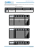
Table 1071: 8-bit FIFO Data Format
# Samples
1
9
1
8
1
7
1
6
1
5
1
4
1
3
1
2
1
1
1
0
9 8 7 6 5 4 3 2 1 0
128 000000 8.6
64 000000 8.6
32 000000 8.5 X
16 000000 8.4 XX
8 000000 8.3
XXX
4 000000 8.2
XX X X
2 000000 8.1 XXXXX
1 000000 8 XXXXXX
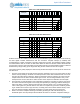
Table 1070: 10-bit FIFO Data Format
# Samples
1
9
1
8
1
7
1
6
1
5
1
4
1
3
1
2
1
1
1
0
9 8 7 6 5 4 3 2 1 0