
User Manual


Apollo3 Blue Datasheet
DS-A3-0p9p1 Page 725 of 909 2019 Ambiq Micro, Inc.
All rights reserved.
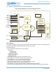
18.2.3 Triggering and Trigger Sources
The ADC block can be initially triggered from one of six sources. Once triggered, it can be repetitively
triggered from counter/timer number three (3). Four of the GPIO pins on the Apollo3 Blue MCU can be
selected as trigger inputs to the ADC through a combination of settings in the PAD configuration registers
in the GPIO block and settings in SLOT configuration registers described below. In addition, there is a
software trigger and a vcomp trigger source. The trigger sources are as follows:
0. ADC_EXT0 (TRIG0) external GPIO pin connection.
1. ADC_EXT1 (TRIG1) external GPIO pin connection.
2. ADC_EXT2 (TRIG2) ADC_EXT3 (TRIG3) VCOMP Voltage Comparator trigger.
3. <Reserved>
4. <Reserved>
5. ADC_SWT software trigger.
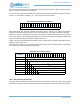
Refer to the ADC Configuration Register in the detailed register information section below. The initial
trigger source is selected in the TRIGSEL field, as shown below. In addition, one can select a trigger
polarity in this register applicable for any of the trigger sources except the software trigger. A number of
GPIO pin trigger sources are provided to allow pin configuration flexibility at the system definition and
board layout phases of development.
The software trigger is effected by writing 0x37 to the software trigger register in the ADC block. Note that
writing 0x37 to the software trigger register will initiate a scan regardless of which trigger source is
selected. However, a hardware trigger source will not initiate a scan if the software trigger has been
selected.
When the ADC is configured for repeat mode, the initial trigger must be initiated by a software trigger and
subsequent scans will be initiated at a repeating rate set by the counter/timer3 configuration. The
discussion of the use of counter/timer three as a source for repetitive triggering is deferred until later in this
chapter.
Finally it is important to note that a trigger event applies to all enabled slots as a whole. Individual slots can
not be separately triggered.
18.2.4 Voltage Reference Sources
The Apollo3 Blue MCU ADC allows one of two reference sources each with two different voltage options to
be used for the analog to digital conversion step:
▪ Internal 2.0V reference source
▪ Internal 1.5V reference source
▪ External 2.0V reference source
▪ External 1.5V reference source
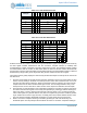
18.2.5 Eight Automatically Managed Conversion Slots
The ADC block contains eight conversion slot control registers, one for each of the eight slots. These can
be thought of as time slots in the conversion process. When a slot is enabled, it participates in a
conversion cycle. The ADC’s mode controller cycles through up to eight time slots each time it is triggered.
For each slot that is enabled, a conversion cycle is performed based on the settings in the slot
configuration register for that slot. Slots are enabled when the LSB of the slot configuration is set to one.
See “One SLOT Configuration Register” on page 726.