
User Manual


Apollo3 Blue Datasheet
DS-A3-0p9p1 Page 723 of 909 2019 Ambiq Micro, Inc.
All rights reserved.
18. ADC and Temperature Sensor Module
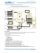
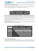
Figure 89. Block Diagram for ADC and Temperature Sensor
18.1 Features
The Analog to Digital Converter (ADC) and Temperature Sensor Module includes a 14 bitmulti-channel
Successive Approximation Register (SAR) ADC as shown in Figure 89.
Key features include:
▪ 15 user-selectable channels with sources including:
- External pins
- 10 single ended
- 2 differential pairs
- Internal voltage (VSS)
- Voltage divider (battery)
- Temperature sensor
▪ Configurable automatic low power control between scans
▪ Optional Battery load enable for voltage divider measurement
▪ Configurable for 14 / 12 / 10 / 8 bit ADC Precision Modes
▪ User-selectable on-chip and off-chip reference voltages
▪ Single shot, repeating single shot, scan, and repeating scan modes
▪ User-selectable clock source for variable sampling rates
▪ Automatically accumulate and scale module for hardware averaging of samples
▪ A 16-entry FIFO and DMA capability for storing measurement results and maximizing MCU sleep time
SLOT0
14b ADC
ADC_I0
ADC_I1
SWT
...
ADC_TT
ADC_ET0
ADC_ET1
Mode
Controller
VREFINT
ADC_REF
Bandgap Ref
ADC_I9
VSS
ADC_ET3
Window
Comparator
...
Temp Sensor
TRIGINT
VIN
HFRC Osc
Digital
Controller
SLOT1
SLOT2
SLOT3
SLOT4
SLOT5
SLOT6
SLOT7
16 deep
FIFO
Calibration
Battery
Resistor
Divider
ADC_ET2
ADC_DIFF0
ADC_DIFF1
VCOMP
DMA