
User Manual


Apollo3 Blue Datasheet
DS-A3-0p9p1 Page 708 of 909 2019 Ambiq Micro, Inc.
All rights reserved.
Clocking to the UART serial logic is generated by a dedicated UARTCLK from the Clock Generator
Module. The frequency of this clock is determined by the desired baud rate. For maximum baud rates, this
clock would be clocked at the 24 MHz maximum as generated the HFRC.
The major functional blocks of the UART are discussed briefly in the subsequent sections.
17.3 Enabling and Selecting the UART Clock
The UART module receives two clocks - UART_clk which is used to derive the UART serial clock and
UART_hclk, which is the bus interface clock of the UART module. Unlike other Apollo3 Blue MCU
modules, the UART requires a bus clock whenever it is transmitting or receiving, so special controls are
required when the UART is to transfer data while the Apollo3 Blue MCU is in a sleep mode and its normal
bus clocks are not operating.
UART_clk is selected in the UARTx_CR_CLKSEL field, with values from 24 MHz to 3 MHz plus a disabled
value NOCLK, and is enabled by the UARTx_CR_CLKEN bit. If the UART is inactive, CLKSEL should be
set to the NOCLK value (0) to minimize power, and the CLKEN bit should be 0. When the UART is active,
the serial clock is created by the baud rate generator based on UART_clk. A higher UART_clk frequency
can produce more precise serial clock frequencies, but will cause the UART to use more power. It is thus
recommended that UART_clk be set to the minimum frequency which produces acceptable serial clocks.
When software is accessing the UART, UART_hclk must be equivalent to the Apollo3 Blue MCU bus clock
frequency of 48 MHz, but for transmit and receive purposes UART_hclk is only required to be at least as
fast as UART_clk. It is thus possible to manage the frequency of UART_hclk to minimize power used by
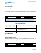
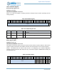
the UART. This is controlled by the CLK_GEN_UARTEN_UARTxEN fields, as defined in the table below.
In general, it is safe to leave the UARTxEN field at 3, which will minimize UART power in sleep modes but
always allow UART register access. Power will be improved if UARTxEN is normally left at 2, and shifted to
3 whenever UART register access is required. Note that the UARTEN register is in the CLK_GEN module
which always has bus access enabled.
17.4 Configuration
The UART Register Block in Figure 88 may be set to configure the UART Module. The data width, number
of stop bits, and parity may all be configured using the UART_LCRH register.
The baud rate is configured using the integer UART_IBRD and UART_FBRD registers. The correct values
for UART_IBRD and UART_FBRD may be determined according to the following equation:
F
UART
/(16·BR) = IBRD + FBRD
F
UART
is the frequency of the UART clock. BR is the desired baud rate. IBRD is the integer portion of the
baud rate divisor. FBRD is the fractional portion of the baud rate divisor.
UARTxEN UART_hclk Function
0 Disable UART_hclk. Select this when the UART is inactive.
1 Force UART_hclk to 48MHz. This is not a recommended mode.
2
Force UART_hclk to match UART_clk. This mode may be used
when the UART is actively transmitting or receiving, or is
expected to receive a transmission. This minimizes power in the
UART but does not allow software access to UART registers.
3
Automatic. In this mode, UART_hclk will be set to 48 MHz when
is awake and set to match UART_clk when is in a sleep mode.
This is a normal safe mode of operation.