
User Manual


Apollo3 Blue Datasheet
DS-A3-0p9p1 Page 707 of 909 2019 Ambiq Micro, Inc.
All rights reserved.
17. UART Module
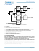
Figure 88. Block Diagram for the UART Module
17.1 Features
The UART Module includes the following key features:
• Operates independently, allowing the MCU to enter a low power sleep mode during communication
• 32 x 8 transmit FIFO and 32 x 12 receive FIFO to reduce MCU computational load
• Programmable baud rate generator capable of a maximum rate of 921,600 bits per second
• Fully programmable data size, parity, and stop bit length
• Programmable hardware flow control
• Support for full-duplex and half-duplex communication
• Loopback functionality for diagnostics and testing
17.2 Functional Overview
Shown in Figure 88, the UART Module converts parallel data written through the APB Slave port into serial
data which is transmitted to an external device. It also receives serial data from an external device and
converts it to parallel data, which is then stored in a buffer until the CPU reads the data.
The UART Module includes a programmable baud rate generator which is capable of operating at a
maximum of 921,600 bits per second. An interrupt generator will optionally send interrupts to the CPU core
for transmit, receive and error events.
Internally, the UART Module maintains two FIFOs. The transmit FIFO is 1-byte wide with 32 locations. The
receive FIFO is 12-bits wide with 32 locations. The extra four bits in the receive FIFO are used to capture
any error status information that the MCU needs to analyze.
APB
UART TX
UART RX
IRQ
APB
Slave
Transmit
FIFO
Register
Block
Receive
FIFO
Interrupt
Generation
Transmit
Interface
Receive
Interface