
User Manual


Apollo3 Blue Datasheet
DS-A3-0p9p1 Page 70 of 909 2019 Ambiq Micro, Inc.
All rights reserved.
The Cortex-M4 allows the user to assign various interrupts to different priority levels based on the
requirements of the application. In this MCU implementation, 8 different priority levels are available.
One additional feature of the M4 interrupt architecture is the ability to relocate the Vector Table to a
different address. This could be useful if the application requires a different set of interrupt service routines
for a particular mode of an application. The software could move the Vector Table into SRAM and reassign
the interrupt service routine entry addresses as needed.
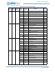
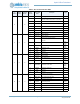
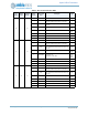
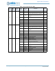
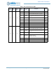
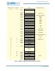
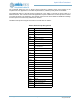
Hardware interrupts are assigned in the MCU to the M4 NVIC as follows:
Table 2: MCU Interrupt Assignments
IRQ Peripheral/Description
NMI Unused
IRQ0 Brownout Detection
IRQ1 Watchdog Timer
IRQ2 RTC
IRQ3 Voltage Comparator
IRQ4
I
2
C / SPI Slave
IRQ5
I
2
C / SPI Slave Register Access
IRQ6
I
2
C / SPI Master0
IRQ7
I
2
C / SPI Master1
IRQ8
I
2
C / SPI Master2
IRQ9
I
2
C / SPI Master3
IRQ10
I
2
C / SPI Master4
IRQ11
I
2
C / SPI Master5
IRQ12 BLE
IRQ13 GPIO
IRQ14 Counter/Timers
IRQ15 UART0
IRQ16 UART1
IRQ17 SCARD
IRQ18 ADC
IRQ19 PDM
IRQ20 MSPI
IRQ21 SW INT
IRQ22 STimer Capture/Overflow
IRQ23-30 STimer Compare[0:7]
IRQ31 Clock Control