
User Manual


Apollo3 Blue Datasheet
DS-A3-0p9p1 Page 692 of 909 2019 Ambiq Micro, Inc.
All rights reserved.
15.2.2 WDT Registers
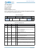
15.2.2.1 CFG Register
Configuration Register
OFFSET: 0x00000000
INSTANCE 0 ADDRESS: 0x40024000
This is the configuration register for the watch dog timer. It controls the enable, interrupt set, clocks for the
timer, the compare values for the counters to trigger a reset or interrupt. This register can only be written
to if the watch dog timer is unlocked (WDTLOCK is not set).
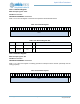
Table 1001: CFG Register
3
1
3
0
2
9
2
8
2
7
2
6
2
5
2
4
2
3
2
2
2
1
2
0
1
9
1
8
1
7
1
6
1
5
1
4
1
3
1
2
1
1
1
0
0
9
0
8
0
7
0
6
0
5
0
4
0
3
0
2
0
1
0
0
RSVD
CLKSEL
INTVAL RESVAL RSVD
RESEN
INTEN
WDTEN
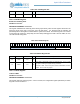
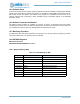
Table 1002: CFG Register Bits
Bit Name Reset RW Description
31:27 RSVD 0x0 RO
This bitfield is reserved for future use.
26:24 CLKSEL 0x0 RW
Select the frequency for the WDT. All values not enumerated below are
undefined.
OFF = 0x0 - Low Power Mode. This setting disables the watch dog timer.
128HZ = 0x1 - 128 Hz LFRC clock.
16HZ = 0x2 - 16 Hz LFRC clock.
1HZ = 0x3 - 1 Hz LFRC clock.
1_16HZ = 0x4 - 1/16th Hz LFRC clock.
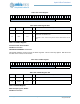
23:16 INTVAL 0xff RW
This bitfield is the compare value for counter bits 7:0 to generate a watch-
dog interrupt.
15:8 RESVAL 0xff RW
This bitfield is the compare value for counter bits 7:0 to generate a watch-
dog reset. This will cause a software reset.
7:3 RSVD 0x0 RO
This bitfield is reserved for future use.
2 RESEN 0x0 RW
This bitfield enables the WDT reset. This needs to be set together with the
WDREN bit in REG_RSTGEN_CFG register (in reset gen) to trigger the
reset.
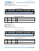
1INTEN 0x0RW
This bitfield enables the WDT interrupt. Note : This bit must be set before
the interrupt status bit will reflect a watchdog timer expiration. The IER
interrupt register must also be enabled for a WDT interrupt to be sent to the
NVIC.