
User Manual

Apollo3 Blue Datasheet
DS-A3-0p9p1 Page 690 of 909 2019 Ambiq Micro, Inc.
All rights reserved.
15. Watchdog Timer Module
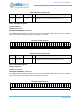
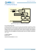
Figure 85. Block diagram for the Watchdog Timer Module
15.1 Functional Overview
The Watchdog Timer (WDT), shown in Figure 85, is used to insure that software is operational, by resetting
the Apollo3 Blue MCU if the WDT reaches a configurable value before being cleared by software. The
WDT can beclocked by one of four selectable prescalers of the always active low-power LFRC clock, but is
nominally clocked at 128 Hz. The WDT may be locked to ensure that software cannot disable its
functionality, in which case the WDTCFG register cannot be updated. An interrupt can also be generated
at a different counter value to implement an early warning function. Note: The RESEN bit in the WDTCFG
register must be set and the WDREN bit in the RSTCFG register must be set to enable a watchdog timer
reset condition.
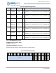
15.2 WDT Registers
Watchdog Timer
INSTANCE 0 BASE ADDRESS:0x40024000
8-bit Counter
128 Hz
8-bit Reset Value
Compare
Control
WDINT
WDRES
CLR
8-bit Interrupt Value
Compare
16 Hz
1 Hz
1/16 Hz