
User Manual


Apollo3 Blue Datasheet
DS-A3-0p9p1 Page 669 of 909 2019 Ambiq Micro, Inc.
All rights reserved.
14. System Timer Module
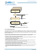
Figure 84. Block Diagram for the System Timer
14.1 Functional Overview
The Apollo3 Blue MCU System Timer (STIMER), shown above in Figure 84, tracks the global
synchronized counter. It can be used for RTOS scheduling and real-time system tracking. This timer is
provided in addition to the other timer peripherals to enable software/firmware to have a simple, globally
synchronized timer source.
The System Timer (STIMER) Module provides real time measurement for all task scheduling, sensor
sample rate calibration, and tracking of real time and calendar maintenance. Key features are:
▪ 32-bit binary counter used for RTOS scheduling decisions.
▪ Eight 32-bit compare and interrupt registers to facilitate light weight scheduling (designs without RTOS).
▪ Accurate scheduling of comparator interrupts
▪ Only offsets from “NOW” are written to comparator registers.
▪ Maintains real time epoch for applications.
▪ Overflow interrupt to allow firmware to keep the extended part (more than 32-bits) of real time epoch.
▪ Time stamping hardware for multiple sensor streams (4 capture registers).
▪ Firmware handling of odd calculations such as Leap Second. It also handles things like surprise/legis-
lated changes to the daylight savings time transition dates.
▪ Firmware handling of 1024 versus 1000 scaling of real time conversions.
▪ Only reset by POA (Power On Analog - system cold reset) so that it retains time across all POI and POR
(system warm reset) events except full power cycles.
▪ Contains three 32-bit NVRAM registers that are only reset by POA to maintain real time offset from
epoch.
32-bit system timer
=
CLK
Comp IRQ
32-bit compare value
( x 8)
32-bit capture registers
( x 4)
GPIO
OVF IRQ
Capture IRQ