
User Manual

Apollo3 Blue Datasheet
DS-A3-0p9p1 Page 656 of 909 2019 Ambiq Micro, Inc.
All rights reserved.
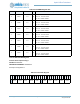
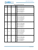
13.21.2.60OUTCFG2 Register
Counter/Timer Output Config 2
OFFSET: 0x0000010C
INSTANCE 0 ADDRESS: 0x4000810C
Pad output configuration 2.
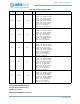
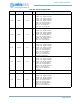
2:0 CFG10 0x2 RW
Pad output 10 configuration
A7OUT2 = 0x7 - Output is A7OUT2.
A6OUT2 = 0x6 - Output is A6OUT2.
A6OUT = 0x5 - Output is A6OUT.
B4OUT2 = 0x4 - Output is B4OUT2.
B3OUT2 = 0x3 - Output is B3OUT2.
B2OUT = 0x2 - Output is B2OUT
ONE = 0x1 - Force output to 1.
ZERO = 0x0 - Force output to 0
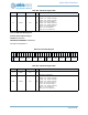
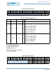
Table 939: OUTCFG2 Register
3
1
3
0
2
9
2
8
2
7
2
6
2
5
2
4
2
3
2
2
2
1
2
0
1
9
1
8
1
7
1
6
1
5
1
4
1
3
1
2
1
1
1
0
0
9
0
8
0
7
0
6
0
5
0
4
0
3
0
2
0
1
0
0
RSVD
CFG29 CFG28 CFG27 CFG26 CFG25
RSVD
CFG24 CFG23 CFG22 CFG21 CFG20
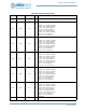
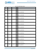
Table 940: OUTCFG2 Register Bits
Bit Name Reset RW Description
31 RSVD 0x0 RO
RESERVED
30:28 CFG29 0x2 RW
Pad output 29 configuration
A7OUT2 = 0x7 - Output is A7OUT2.
A6OUT2 = 0x6 - Output is A6OUT2.
A3OUT2 = 0x5 - Output is A3OUT2.
A7OUT = 0x4 - Output is A7OUT.
A1OUT = 0x3 - Output is A1OUT.
B5OUT2 = 0x2 - Output is B5OUT2
ONE = 0x1 - Force output to 1.
ZERO = 0x0 - Force output to 0
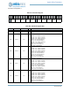
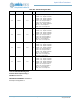
Table 938: OUTCFG1 Register Bits
Bit Name Reset RW Description