
User Manual


Apollo3 Blue Datasheet
DS-A3-0p9p1 Page 577 of 909 2019 Ambiq Micro, Inc.
All rights reserved.
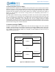
Note that for the Pulse and Count modes, the CMPR2/3 registers can always be configured so that OUT2
matches OUT. This provides more flexibility in the pin assignments, as any OUT2 connection can be used
as the corresponding OUT function if a separate OUT2 function is not required. For a single 32-bit pattern
from a timer, OUT2 can be configured in the CMPR2/3 registers to produce the same pattern as OUT.
The OUT and OUT2 outputs of each CTIMER will be toggling whenever the CTIMER is enabled,
independent of any pin connections configured for it. This allows these signals to be used as clocks and
triggers for other CTIMERs even when they are not being used as pin outputs.
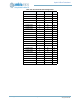
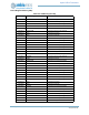
Example flow is illustrated below:
1) Pickthepadyouwanttouse,fromcolumnPad(FNCSEL).
2) Setthatpad’sFN CSELtothevalueinparentheses.
3) Determine whichoftheoutputsincolumns 2‐7youwanttousetodrivethispin.
4) SettheOUTCFG0/1/2/3_CFGxbitfieldtothevalueof2through7toselectthedesired
CTIMER
output.
5) ClearthebitinCTENCFGcorrespondingtotheCTxxvaluethatmatchesthepad,tomakeitan
output.
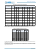
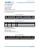
13.21CTIMER Registers
Counter/Timer
INSTANCE 0 BASE ADDRESS:0x40008000
The Counter/Timer block contains 8 sixteen bit counter or timer functions. Each pair of these counters can
be cascaded into 32 bit Counter/Timer functions.