
User Manual


Apollo3 Blue Datasheet
DS-A3-0p9p1 Page 571 of 909 2019 Ambiq Micro, Inc.
All rights reserved.
13.18.2Counting Buck Converter Edges
Apollo3 includes three separate buck converters which provide power for the Processor power domain
(BUCKA), the Memory power domain (BUCKB) and the BLE interface module (BUCKBLE). Each CTIMER
may be connected to a pulse stream from any of the three analog Buck Converters. One pulse is
generated each time the Buck Converter inserts charge into the capacitor, and therefore the number of
pulses is a good indication of the amount of energy used by the corresponding power domain in a
particular time period.
A possible option to determine energy consumption is as follows. Two counters could be configured with
FN = 6 so that they count continuously. One is supplied a Buck Converter pulse stream as its clock, and
the other is supplied with a divided version of the LFRC clock to avoid creating extra power consumption
due to the power measurement. Once configured such, the two counters should be enabled
simultaneously, and after some period of system operation they should be disabled and read. The LFRC
count value would now define how much real time has elapsed, and the Buck Converter count value would
define how much energy was consumed in that time.
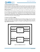
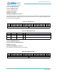
13.19Interconnecting CTIMERs
The OUT or OUT2 output of one CTIMER may be used as either the Trigger or the clock of another
CTIMER. Figure 83 shows the interconnection structure for two example CTIMERs, where p and q are A
or B and x and y are 0 through 7. The selection of the actual clock or trigger interconnection is made within
each CTIMER. The interconnection Matrix is not complete, as each CTIMER can select from only 15
triggers and 12 external clocks.
Figure 83. CTIMER Interconnection
CTIMERpx
CTIMERqy
ctimerpx_out
ctimerpx_out2
ctimerpx_extclk
ctimerpx_trig
ctimerqy_out
ctimerqy_out2
ctimerqy_extclk
ctimerqy_trig
11
15
11
15
Interconnection Matrix (no logic)
...